
01Where you will see the error code
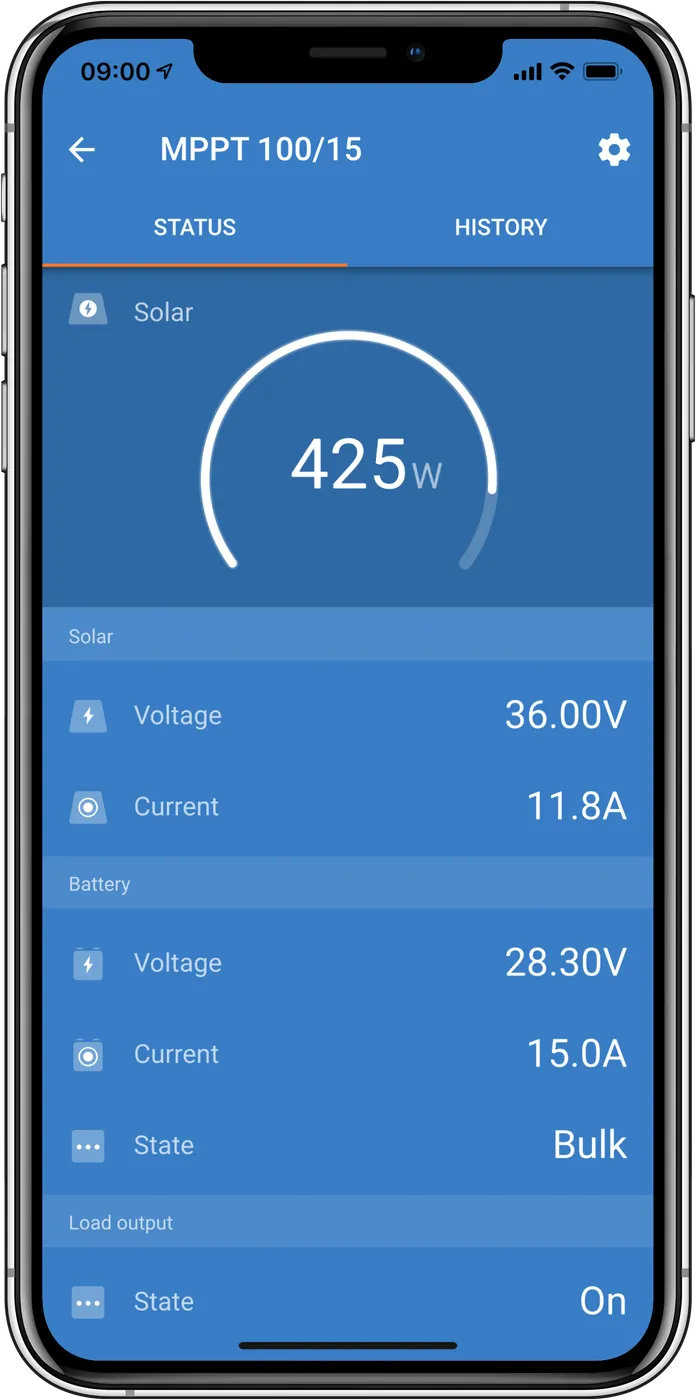
- VictronConnect — on the device status screen (Bluetooth or VE.Direct–USB interface); the latest errors are also in the history.
- GX device and VRM portal — if the controller is connected to GX via VE.Direct or VE.Can.
- Orion XS — error and warning codes are shown in the VictronConnect app or on the connected GX device. Orion XS uses some codes from this list, and also has its own warnings 150–162.
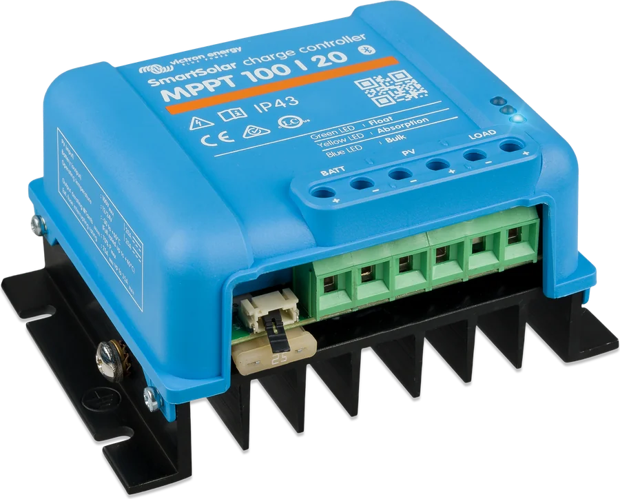
- LEDs — small controllers signal an error by flashing LEDs; you can check the meaning of a given pattern in the LED decoder, and the code number in the app.
02Battery and sensors
Battery temperature too high
The charger stops charging to protect the battery.
Battery temperature can be provided by an external sensor (e.g. Smart Battery Sense or BMV) or by the charger if it has that measurement.
Orion XS: if no external battery temperature sensor is connected, the charger assumes that at start-up and in float the temperature is equal to the battery temperature — an overheated charger is then treated as an overheated battery (Orion XS manual).
Clears itselfafter the battery temperature drops.
Original: “Battery temperature too high” · Victron source
Battery voltage too high
This may be caused by another device charging the same battery or by a fault in the controller.
The error also appears if you select a lower system voltage in the settings (12, 24, 48 V) than the voltage of the connected battery.
Clears itselfafter the battery voltage drops.
Original: “Battery voltage too high” · Victron source
External temperature sensor failure
Check that the T-sense connector is correctly connected to the external temperature sensor.
Most common cause: the T-sense connector is connected to the BAT+ or BAT− terminal.
Clears itselfafter correct connection.
Original: “Remote temperature sensor failure” · Victron source
Temperature sensor connection lost
Check that the T-sense connector is correctly connected to the external temperature sensor.
Does not clear itself
Original: “Remote temperature sensor failure (connection lost)” · Victron source
External battery voltage sense failure
Check that the V-sense connector is correctly connected to the battery terminals.
Most common cause: reverse polarity of the V-sense wires on the BAT+ / BAT− terminals.
Original: “Remote battery voltage sense failure” · Victron source
Battery voltage sense connection lost
Check that the V-sense connector is correctly connected to the battery terminals.
Original: “Remote battery voltage sense failure (connection lost)” · Victron source
High battery ripple voltage
High DC ripple voltage is usually caused by loose DC cable connections or cables that are too thin.
After shutting down because of ripple, the inverter waits 30 s and starts again. After three such restarts, if it shuts down again within 30 s each time, it stops trying — then switch it off and back on.
Long-term high ripple shortens the inverter’s service life.
Original: “Battery high ripple voltage” · Victron source
Battery temperature too low
The charger stops charging so it does not charge LiFePO4 batteries at low temperature — this damages the cells.
Original: “Battery low temperature” · Victron source
03Controller and charger
Controller overheating despite current limit
Check the ambient temperature and whether anything is blocking the heatsink.
Clears itselfafter cooling down.
Original: “Controller overheated despite reduced output current” · Victron source
Controller over-current
Possible causes of overcurrent at the battery terminals: switching on or off a very large load on the battery side, a sudden change in solar irradiance (temporary excess power in the MPPT), AC output overload on the inverter.
What to do: improve cooling (a cooler device will accept more current), reduce the inverter load, charge the battery before using the inverter (at higher battery voltage, the same power means lower current).
Clears itselfIf not — disconnect the controller from all sources, wait 3 minutes and switch it back on.
Original: “Controller over-current” · Victron source
Maximum Bulk time exceeded
Solar controllers: this protection was present in early devices (2015 and earlier), then removed. If you see this error, update the firmware to the latest version; if it does not disappear — restore factory settings and configure the controller again.
AC chargers: this protection is enabled by default in Skylla-i and Skylla IP44. The error appears when, after 10 h of charging, the battery has not reached absorption voltage — it is intended to detect a shorted cell and stop charging.
Original: “Maximum Bulk-time exceeded” · Victron source
Current sensor issue
Current measurement is out of range.
Disconnect all wires and reconnect them to restart the controller. Make sure the controller negative (PV negative / battery negative) does not bypass the controller.
If the error does not clear, it may be a hardware fault — contact the dealer.
Does not clear itself
Original: “Current sensor issue” · Victron source
Internal temperature sensor failure
The internal temperature measurement is out of range.
Disconnect all wires and reconnect them to restart the device. If the error does not clear, it may be a hardware fault — contact the dealer.
Does not clear itself
Original: “Internal temperature sensor failure” · Victron source
Fan failure
The fan is powered, but the circuit does not detect current draw — it is most likely faulty or blocked. It may be a hardware fault — contact the dealer.
Applies to: Skylla IP44 and Skylla IP65 chargers only
Original: “Fan failure” · Victron source
Terminal overheated
The power terminals have overheated. Check the wiring — including cable type and strands — and tighten the screws if possible.
Clears itself
Original: “Terminal overheated” · Victron source
Battery short circuit
Overcurrent on the battery side. This may occur when the battery is connected by a contactor, or when the charger starts without a battery but is connected to an inverter with high input capacitance.
Clears itselfIf not — disconnect the controller from all sources, wait 3 minutes and switch it back on. If the error persists, the controller is probably faulty.
Original: “Charger short circuit” · Victron source
Power stage issue
Disconnect all wires and reconnect them. If the error persists, the controller is probably faulty.
The error was introduced in firmware v1.36. After an update, it may seem as though that caused it — but the controller was already not working fully correctly, and the new firmware only exposed it. The device needs to be replaced.
Does not clear itself
Original: “Power stage issue” · Victron source
Over-Charge protection
The battery is disconnected so it cannot be overcharged.
Possible causes: the solar array is too large — with too many panels in series, the battery voltage can no longer be reduced (consider wiring more panels in parallel); incorrect battery settings (especially absorption and float voltages); another charger in the system is raising the battery voltage above the expected level.
Clears itselfwhen the battery voltage drops below float voltage.
Original: “Over-Charge protection” · Victron source
04PV panels
PV over-voltage
The open-circuit voltage (Voc) of the solar array is critical for this controller. Check the configuration and, if necessary, rewire the panels differently (fewer in series).
Note: according to the SmartSolar controller manuals, exceeding the maximum PV voltage can damage the controller, and such damage is not covered by the warranty. Voc rises in cold weather — calculate this in the MPPT calculator.
Orion XS: Error 33 means input voltage too high and clears itself when the input voltage drops to a safe level (Orion XS manual).
Clears itselfwhen the PV voltage drops to a safe level.
Original: “PV over-voltage” · Victron source
PV over-current
The current from the solar array exceeded the rated current. The error may also be caused by an internal fault.
Disconnect the controller from all sources, wait 3 minutes and switch it back on. If the error persists, the controller is probably faulty — contact the dealer.
Original: “PV over-current” · Victron source
PV over-power
Update the firmware to at least v1.08 — the causes of this error were removed in that version.
With firmware v1.08 or later, the error means the internal DC voltage is too high. If it does not clear itself, disconnect the device from all sources, wait 3 minutes and switch it back on. If the error persists — the device is probably faulty.
Clears itself(with firmware from v1.08). · Applies to: MPPT RS, Inverter RS, Multi RS
Original: “PV over-power” · Victron source
PV input shut down
The PV input was internally shorted to protect the battery from overcharging. Before any other steps, update the firmware to the latest version.
Possible causes: the battery voltage is set incorrectly (12/24/36/48 V) — set the correct one in VictronConnect; another device on the same battery has a higher charging voltage (for example a MultiPlus set to equalise at 17 V, which was not set in the controller).
Clearing: Err 38 and Err 84–87 — disconnect the panels and battery, wait 3 minutes, connect the battery first, then the panels. Err 39 — the controller will resume operation on its own when the battery voltage drops below the maximum set voltage (usually equalisation or absorption); this may take a minute. Err 80–83 — first disconnect the panels and battery, then carry out the reset procedure specified in Victron’s documentation for these errors; without this procedure, the reset should not be considered complete.
If the error persists, the controller is probably faulty.
Originally: “PV Input shutdown” · Victron source
PV input failed to shut down
If the controller cannot shut down the PV input, it switches to safe mode to protect the battery from overcharging or excessive voltage at the terminals: it stops charging and disconnects its own output. The controller is then faulty.
Originally: “PV Input failed to shutdown” · Victron source
05Inverter and isolation (RS devices and inverters)
Inverter shutdown — PV isolation
PV panel insulation resistance is too low. Check the wiring of the PV array and the panel insulation — the inverter will restart automatically once the problem has been cleared.
To resume AC operation, you can disconnect the PV array with the PV isolator.
Originally: “Inverter shutdown (PV isolation)” · Victron source
Inverter shutdown — PV leakage current
Leakage current to earth in the PV array exceeds the permitted 30 mA. Check the wiring of the PV array and the panel insulation.
To resume AC operation, you can disconnect the PV array with the PV isolator.
Originally: “Inverter shutdown (PV isolation)” · Victron source
Inverter shutdown — ground fault
The voltage difference between the neutral wire and earth is too high.
Inverter or Multi without a grid connection: the internal grounding relay is on, but the voltage across it is too high — the relay may be faulty.
Multi connected to the grid: the installation is missing an earth conductor or it is incorrectly connected, or the phase and neutral conductors have been swapped.
Check the installation and restart the device with the switch.
Does not clear itself
Originally: “Inverter shutdown (Ground Fault)” · Victron source
Inverter overload / peak current
Some loads, such as motors and pumps, draw a high inrush current at start-up, which can exceed the overcurrent protection threshold — the output voltage then drops quickly to limit the current. The inverter can briefly supply more than its rated power; if this time is exceeded, it shuts down.
After three restarts, if an overload occurs again within 30 s each time, the inverter shuts down permanently — switch it off and on again. If the error recurs, reduce the AC output load.
Originally: “Inverter overload, Inverter peak current” · Victron source
Inverter temperature too high
High ambient temperature or prolonged heavy loading can cause an overtemperature shutdown.
Reduce the load or move the inverter to a better ventilated location and check that nothing is blocking the fan outlets. The inverter will restart after 30 s and will not remain shut down after multiple attempts.
Originally: “Inverter temperature too high” · Victron source
Inverter output voltage
When battery voltage is low and a large load is connected to the AC output, the inverter cannot maintain the correct output voltage. Charge the battery or reduce the AC load.
Originally: “Inverter output voltage” · Victron source
Inverter output voltage
When battery voltage is low and a large load is connected to the AC output, the inverter cannot maintain the correct output voltage. Charge the battery or reduce the AC load.
If the error appears immediately after switching the inverter on (with no load) and the battery is full, the replaceable internal fuse has probably blown — contact a Victron dealer.
Originally: “Inverter output voltage” · Victron source
Inverter self-test failed
Before enabling the output, the inverter performs diagnostic tests. If one fails, it shows an error and does not switch on.
Try switching the inverter off and on again. If the error persists, the inverter is probably faulty.
Originally: “Inverter self test failed” · Victron source
AC voltage on inverter output
Before the inverter is switched on, there is already AC voltage on the AC out terminals. Check that the output is not connected to a mains socket or another inverter.
Check the installation and restart the device with the switch.
Does not clear itself
Originally: “Inverter ac voltage on output” · Victron source
AC-IN1 relay test fault
The automatic test of the disconnecting component failed. This usually means a faulty (stuck) relay in the AC input stage.
Originally: “ACIN1 relay test fault” · Victron source
06Parallel operation, BMS and device network
Communication warning (Information 65)
Communication with one of the parallel-running controllers has been lost. To clear the warning, switch the controller off and on again.
Originally: “Communication warning” · Victron source
Incompatible device (Information 66)
The controller is running in parallel with another one that has different settings or a different charging algorithm. Make the settings consistent and update the software of all chargers to the latest version.
This message also appears when MPPT controllers are connected to a GX device and at the same time configured for a VE.Smart network. Disable VE.Smart Networking and use DVCC in the GX device.
Originally: “Incompatible device” · Victron source
Lost connection with BMS
The charger is configured to be controlled by the BMS, but it is not receiving messages from it. It then stops charging by reducing the output voltage to the battery’s base voltage (12/24/36/48 V) — this is intentional so the system can recover from a deep discharge on its own.
Solar chargers show this error only when there is solar power — they do not show it at night. If the problem is persistent, the error appears in the morning and disappears at night.
Solution: check the connection between the charger and the BMS.
Chargers switch to BMS control automatically when connected to it (directly or via GX), and switching the power off does not clear this. When moving to a system without a BMS: on chargers with an LCD display, change the “BMS” setting from “Y” to “N” in the menu (item 31); on others, restore factory settings in VictronConnect and set it up again.
Orion XS: the output voltage drops to the base voltage (12 V) 15 seconds after communication is lost, and the error appears only after 3 minutes — to allow the BMS time to reconnect and to avoid repeated notifications. The error is shown only when the device is ready to charge, not in the “off” state. In VictronConnect this looks like a transition from bulk straight to float; once communication is restored, the charger returns to bulk (Orion XS manual).
Originally: “BMS Connection lost” · Victron source
Network misconfigured (68)
Applies to SmartSolar/BlueSolar MPPT VE.Can (firmware from v1.04) and SmartSolar VE.Direct MPPT (v1.47).
SmartSolar VE.Direct: update the firmware to v1.48 or later. MPPT VE.Can: update the firmware; if the error persists, the controller is connected at the same time with a VE.Direct cable and a VE.Can cable — this is not supported. Disconnect one of the cables; the controller will resume operation within a minute.
Context: the controller is receiving the same information (for example battery voltage) from two sources with the same priority (VE.Can and VE.Direct). Bluetooth (VE.Smart) has a lower priority and is ignored if it conflicts with VE.Can.
Originally: “Network misconfigured” · Victron source
Network misconfigured (69)
Devices on the same CAN bus have different system configurations. Set all of them to “Single Phase” or “Three Phase”, and to 50 Hz or 60 Hz. The devices remain switched off until the configuration is corrected.
Applies to: Inverter RS and Multi RS, firmware from v1.11
Originally: “Network misconfigured” · Victron source
Incorrect grid configuration (70)
Inverter RS cannot operate in parallel with Multi RS or with a Transfer Switch.
Applies to: Inverter RS, firmware from v1.11
Originally: “Network misconfigured” · Victron source
Incorrect grid configuration (71)
There are devices on the CAN bus with incompatible firmware. Update all of them to the same version — until then they remain disabled.
Applies to: Inverter RS and Multi RS, firmware from v1.11
Originally: “Network misconfigured” · Victron source
Phase rotation
Check that the phase rotation is correct: L1 → L2 → L3. The inverters continue to operate, but they do not connect to the grid until the problem is resolved.
Applies to: Inverter RS and Multi RS, firmware from v1.12
Originally: “Phase rotation” · Victron source
Multiple AC inputs
Only one active grid connection is allowed on each phase — remove or disable the extra ones. The inverters continue to operate, but they do not connect to the grid until the problem is resolved.
Applies to: Inverter RS and Multi RS, firmware from v1.12
Originally: “Multiple AC inputs” · Victron source
Too many units in parallel
The number of inverters connected in parallel does not match the capacity of the Multi RS input relay or Transfer Switch. The firmware does not support parallel units together with a grid connection — any such combination with more than one Multi RS per phase will trigger this error. Multi RS currently supports 3 units in a three-phase system.
The inverters continue to operate, but they do not connect to the grid until the problem is resolved.
Applies to: Inverter RS and Multi RS, firmware from v1.12
Originally: “Too many units in parallel” · Victron source
Incorrect grid configuration (75)
Three-phase operation is not yet certified for the selected grid code. The inverters continue to operate, but they do not connect to the grid.
Applies to: Multi RS, firmware from v1.19
Originally: “Network misconfigured” · Victron source
Incomplete network
The inverters have shut down because there are too few devices for grid operation. Check that all required devices are powered on and that the CAN cables are connected correctly. Related settings in VictronConnect: “Prevent CAN network islanding”, “Number of inverters in the system” and “Continue with missing phase”.
Applies to: Inverter RS and Multi RS
Originally: “Network incomplete” · Victron source
Settings sync disabled
Warning: in the device network, some units have system settings synchronisation enabled and some do not. The devices continue to operate; to clear the warning, enable or disable synchronisation on all of them.
Applies to: Inverter RS and Multi RS, firmware from v1.29
Originally: “Settings sync disabled” · Victron source
07Firmware and internal faults
Processor temperature too high
The error clears after the processor cools down. If it persists, check the ambient temperature and that nothing is blocking the air inlets and outlets; check the installation manual for cooling requirements. If it still persists, the controller is probably faulty.
Originally: “CPU temperature too high” · Victron source
Calibration data lost
If the device is not working and error 116 is active, the device is faulty — contact your dealer for a replacement.
If the error is only in the history and the device works normally, you can ignore it (the first units left the factory with this entry in the history).
SmartSolar (not BlueSolar): updating to firmware v1.4x is irreversible — rolling back to an earlier version gives error 116; reinstalling v1.4x fixes it.
Originally: “Calibration data lost” · Victron source
Incompatible firmware
The firmware update did not finish and the device is only partially updated (for example, it was out of range during a wireless update, the cable disconnected, or the power failed).
Repeat the update with the correct firmware file: via VictronConnect (also over Bluetooth) or remotely through the VRM portal if the GX device is connected to VRM.
Originally: “Incompatible firmware” · Victron source
Settings lost
The controller cannot read the configuration and has stopped.
Restore factory settings (in VictronConnect — the three dots in the top right corner), disconnect the controller from all sources, wait 3 minutes, power it on again and configure it again.
The manufacturer asks you to report this error through your dealer (with the firmware version and screenshots from VictronConnect or the installation address in VRM), because it should not occur.
Does not clear itself
Original: “Settings data lost” · Victron source
Internal supply voltage error
When the internal power supplies are switched on, the device runs diagnostics. This error means that something is wrong with one of the internal supply voltages.
Check the installation and restart the device with the switch. If the error persists, the device is probably faulty.
Does not clear itself
Applies to: Orion XS (according to the Orion XS manual).
Originally: “Internal supply voltage error” · Orion XS manual
Tester failure
If the device is not working and error 121 is active, the device is faulty — contact your dealer for a replacement.
If the error is only in the history and the device works normally, you can ignore it (an entry from the first factory start-up).
Originally: “Tester fail” · Victron source
Corrupted history data
Clear the history data in VictronConnect to remove the error.
Does not clear itself
Applies to: Orion XS (according to the Orion XS manual).
Originally: “History data corrupted” · Orion XS manual
Internal DC voltage error
The device tests its internal DC-DC converter when it starts up; the error means there is a problem with that converter. Check the installation and restart the device with the switch. If the error persists, the device is probably faulty.
Does not clear itself
Originally: “Internal DC voltage error” · Victron source
Internal DC voltage measurement error
The internal (high) voltage measurement does not meet the criteria. First update the firmware to v1.08 or later — in older versions the limits were too strict and the error could appear falsely in the morning and evening.
If the error occurs after the update, the measurement circuit is faulty. Check the installation and restart the device with the switch; if the error persists, the device needs repair or replacement.
Does not clear itself· Applies to: MPPT RS, Inverter RS, Multi RS
Originally: “Internal DC voltage error” · Victron source
Residual current sensor error
The residual current sensor failed its self-test. Check the installation and restart the device with the switch. If the error persists, the device needs repair or replacement.
Does not clear itself
Originally: “Internal GFCI sensor error” · Victron source
Internal supply error
The device tests its internal supply voltages when they are switched on; the error means there is a problem with one of them. Check the installation and restart the device with the switch. If the error persists, the device is probably faulty.
Does not clear itself
Originally: “Internal supply voltage error” · Victron source
08Orion XS warnings (Warning 150–162)
Battery temperature too high
The output voltage is reduced to the nominal voltage (12 V) to avoid damaging the battery.
If no external battery temperature sensor is connected, the charger assumes that at start-up and in float the battery temperature is equal to the battery temperature — an excessively hot charger is then treated as an excessively hot battery.
Clears itselfafter the battery temperature drops.
Original: “Battery temperature too high” · Orion XS manual
Battery temperature too low
Charging has stopped because the battery temperature is too low. This is part of battery protection and does not necessarily indicate a fault — charging lithium batteries at low temperature can damage them.
If you think the protection should not have activated, ask the installer to change the relevant setting. More: LiFePO₄ in winter.
Original: “Battery temperature too low” · Orion XS manual
Charge current limited due to charger high temperature
The current is being limited to control the internal temperature. Check the ambient temperature and whether the Orion XS is installed so it can cool properly.
Clears itselfafter the charger has cooled down.
Original: “Current derate due to controller high temperature” · Orion XS manual
Short circuit detected
An overcurrent was detected on the battery side.
If the warning does not clear itself, disconnect the charger from all power sources, wait 3 minutes and switch it back on. If the warning persists, the charger is probably faulty.
Clears itself
Original: “Short circuit detected” · Orion XS manual
Power stage issue
The rated current is limited to half the nominal current.
Disconnect all cables and reconnect them. If the warning persists, the charger is probably faulty.
Does not clear itself
Original: “Power stage issue” · Orion XS manual
09Multi HS19 Solar (high-voltage battery)
The Multi HS19 Solar 15k has its own error-code list — some numbers are the same as on RS devices, but the meaning can differ (for example, Err 10, 15 and 16 concern a 650–1000 V battery and its communication). Device description: Multi HS19 Solar datasheet.
Battery voltage too high
Another device may be charging the battery, or the device may be faulty.
Clears itselfafter the battery voltage drops.
Applies to: Multi HS19 Solar 15k
Original: “Battery voltage too high” · Multi HS19 Solar manual
Battery voltage too low
The battery voltage is below 650 V and the inverter cannot start. Charge the battery from PV or externally.
Applies to: Multi HS19 Solar 15k
Original: “Battery voltage too low” · Multi HS19 Solar manual
Battery relay fault
Internal relay test failed. The device will try 3 times by itself; then check the installation and restart using the switch. If the error persists — repair or replacement.
Applies to: Multi HS19 Solar 15k
Original: “Battery relay fault” · Multi HS19 Solar manual
Battery not found
No communication with the battery for more than 3 minutes, or the voltage reported by the BMS does not match the voltage at the DC terminals. After 3 automatic attempts, check the installation and communication, then restart. If it persists — battery or device fault.
Applies to: Multi HS19 Solar 15k
Original: “Battery not found” · Multi HS19 Solar manual
Temperature sensor connection lost
After 3 automatic attempts, check the installation and restart. If it persists — repair or replacement.
Applies to: Multi HS19 Solar 15k
Original: “Charger temperature sensor connection lost” · Multi HS19 Solar manual
Charger fan missing
The fan is powered, but not drawing current — faulty or blocked. Contact the seller.
Applies to: Multi HS19 Solar 15k
Original: “Charger fan missing” · Multi HS19 Solar manual
Internal error
Diagnostic test failed. After 3 automatic attempts, check the installation and restart. If it persists — repair or replacement.
Applies to: Multi HS19 Solar 15k
Original: “Internal error” · Multi HS19 Solar manual
PV insulation resistance too low
Check the cabling and insulation of the panels.
Clears itselfthe device restarts itself after the problem has been removed.
Applies to: Multi HS19 Solar 15k
Original: “PV isolation resistance too low” · Multi HS19 Solar manual
Ground fault
Leakage current in the PV or battery circuit above 30 mA. Check the cabling and insulation, then restart using the switch.
Applies to: Multi HS19 Solar 15k
Original: “Ground fault” · Multi HS19 Solar manual
Ground relay fault
N–PE voltage too high. Without mains — the ground relay may be faulty. With mains — PE not connected or connected incorrectly, or L and N are swapped.
Applies to: Multi HS19 Solar 15k
Original: “Ground relay fault” · Multi HS19 Solar manual
Inverter overload
Inrush currents (motors, pumps) exceed the threshold. Restart after 30 s; after 3 restarts and another overload within 30 s, the inverter switches off — reduce the load, switch the device off and on.
Applies to: Multi HS19 Solar 15k
Original: “Inverter overload” · Multi HS19 Solar manual
Inverter temperature too high
High ambient temperature or prolonged heavy load. Reduce the load, improve ventilation, check the fan outlets.
Clears itselfrestart after 30 s, with no permanent shutdown.
Applies to: Multi HS19 Solar 15k
Original: “Inverter temperature too high” · Multi HS19 Solar manual
AC input relay fault
Failed switch test, usually a welded contact. After 3 automatic attempts, check the installation and restart. If it persists — repair or replacement.
Applies to: Multi HS19 Solar 15k
Original: “AC input 1 relay fault” · Multi HS19 Solar manual
Calibration data lost
The device is faulty — replacement by the seller.
Applies to: Multi HS19 Solar 15k
Original: “Calibration data lost” · Multi HS19 Solar manual
Invalid firmware
The update did not complete (signal loss, disconnected cable, power outage). Repeat it via VRM (with a GX device) or VictronConnect.
Applies to: Multi HS19 Solar 15k
Original: “Invalid firmware” · Multi HS19 Solar manual
Incompatible hardware
Disconnect the device from all power sources, wait 3 minutes and switch it on. If it persists — replacement by the seller.
Does not clear itself
Applies to: Multi HS19 Solar 15k
Original: “Incompatible hardware” · Multi HS19 Solar manual
Settings lost
Restore factory settings in VictronConnect, disconnect from all power sources for 3 minutes, switch on and configure again.
Does not clear itself
Applies to: Multi HS19 Solar 15k
Original: “Settings data lost” · Multi HS19 Solar manual
Precharge failed
Problem in the start-up sequence. After 3 automatic attempts, check the installation and restart. If it persists — repair or replacement.
Applies to: Multi HS19 Solar 15k
Original: “Precharge failed” · Multi HS19 Solar manual
DC voltage measurement error
Update the firmware first, then check the installation and restart. If it persists — repair or replacement.
Does not clear itself
Applies to: Multi HS19 Solar 15k
Original: “Internal DC voltage measurement error” · Multi HS19 Solar manual
Devices this applies to
 SmartSolar MPPT 75/10–100/20Small solar controllers with Bluetooth for campervans, boats and cabins.
 SmartSolar MPPT RS 450Isolated controller for up to 450 V from panels for 48 V battery banks.
 Inverter RS Smart48 V to 230 V inverter with Bluetooth and VE.Can; charging from an external PV inverter on the AC output.
 Multi RS SolarInverter/charger 48 V, 6 kVA, with two 450 V MPPT trackers — a hybrid for an off-grid cabin and 48 V systems.
 Multi RSInverter/charger 48 V, 6 kVA, without a built-in MPPT — PV via separate solar charge controllers or a PV inverter on the AC output.
 Multi RS19 SolarInverter/charger 48 V, 6 kVA, with two 450 V MPPTs in a 19" enclosure — for a rack cabinet together with batteries.
 Multi HS19 SolarThree-phase 15 kW hybrid inverter with four MPPTs (32 kW PV) and a 650–1000 V high-voltage battery — 19" enclosure for a cabinet.
 Orion-Tr SmartDC-DC charger or converter 12/24/48 V up to about 400 W, in isolated and non-isolated versions; can be connected in parallel.
 Orion XSDC-DC charger 50/70 A from the alternator, including with a smart alternator.
 Smart Battery SenseWireless battery voltage and temperature sensor for controllers and chargers via VE.Smart.
 BMV-712 SmartBattery monitor with display, alarm and programmable relay.
 MultiPlusInverter/charger 800 VA–20 kW: PowerAssist, UPS under 20 ms, parallel and three-phase operation.
 Skylla-i, Skylla-TG, Skylla-IP65Professional 24 and 48 V chargers up to 100 A (Skylla-IP65 also 12 V) — for boats and ships, vehicles and use as a power supply.
What next
The controller is not charging and there is no error code? Go through the diagnostics for “MPPT not charging”. Orion XS not charging — “Orion XS not charging”. If the manufacturer indicates a hardware fault, contact the seller or the installer from whom the device was purchased for repair or replacement.
Sources
- Multi HS19 Solar manual — Troubleshooting chapter (HTML version, as of 22 September 2026)victronenergy.com · EN
- Victron Energy — MPPT Solar Charger Error Codes (as of 10 February 2026)victronenergy.com · EN
- SmartSolar MPPT 75/10 – 100/20 manual (PV overvoltage warning)victronenergy.com · EN
- Orion XS 12/12-50A, 12/12-70A and Orion XS 1400 manuals — section 5.7 Error and warning code overview (HTML version, as of 21 September 2026; code list is identical for all three)victronenergy.com · EN