
01First check
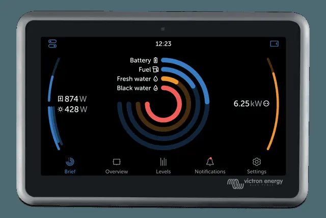
- VE.Bus error code in the GX device, VRM or VictronConnect — if there is one, start with the VE.Bus codes. With this problem, most often: 8, 11, 24 and 128.
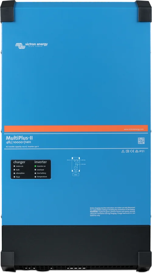
- LEDs on the device — their meaning is shown by the MultiPlus-II LED decoder.
- Is the device switched on — switch in the “On” position (in the “Off” position neither the inverter nor the charger works).
Voltage measurements at the AC terminals and wiring changes should be carried out by a qualified electrician, and only they may change the settings described below; before making any changes, read the manual carefully, and disconnect the AC input while configuring the charger. Use VEConfigure or VictronConnect with the MK3-USB interface (VE.Bus–USB) and an RJ45 UTP cable — the VE.Bus Smart dongle (Bluetooth) lets you monitor the device, switch it on and off, and change the AC input current limit — changing settings requires the MK3-USB interface.
02Step-by-step diagnosis

1Is there voltage at the AC input terminals?
Check the AC input protection and the source itself: the breaker or fuse before the device, power at the hook-up post, the cable and the plugs. According to the troubleshooting table, the breaker or fuse on the AC input may trip because of overload or a short circuit on AC-out-1 or AC-out-2.
Go to step 2.
Remove the overload or short circuit on the AC outputs and switch the breaker back on or replace the fuse. Also check the source (post, generator).
2Are the voltage and frequency within the set range?
MultiPlus-II synchronises with the AC input only when the voltage and frequency are within the set range:
- Input voltage range — adjustable lower limit 180–230 V (factory setting 180 V), upper limit 230–270 V.
- Frequency range — 50 Hz, 60 Hz or 45–65 Hz (factory setting 45–65 Hz).
Measure the source voltage and frequency under load. With a long extension lead at a campsite or a weak hook-up, the voltage may drop below the lower limit.
3Is the problem only with the generator?
The manual describes four settings that help with generators:
- UPS function (enabled by default) — the voltage from some small generators is too unstable and distorted, and MultiPlus-II then switches to inverter operation repeatedly. Manufacturer’s recommendation: switch off the UPS function if the device does not synchronise with the generator or keeps switching back to inverter mode. Switching to inverter mode then takes a little longer, but this does not affect most devices.
- Dynamic current limiter — for inverter generators that slow down at low load. MultiPlus-II then starts with a low draw from the generator and gradually increases it to the set limit, giving the engine time to speed up. It is also used with conventional generators that respond slowly to load changes.
- WeakAC — with heavily distorted voltage, the charger may charge very little or not at all. When WeakAC is enabled, the charger also accepts distorted voltage, but the maximum charge current drops by about 20%. The manufacturer notes that this need is rare, and recommends enabling the dynamic current limiter at the same time, and if necessary reducing the charge current so as not to overload the generator.
- Lower voltage limit for generators with AVR — the factory setting of 180 V can cause the system to shut down with synchronous generators with an AVR regulator (that is most generators from 10 kVA up). This happens when the generator is stopping, while the AVR is trying to maintain 230 V at falling speed. Solution: raise the lower limit to 220 V or disconnect the inverter from the generator with an AC contactor before the generator receives the stop signal.
4Is the system deliberately ignoring the AC input?
In systems with inverter priority (the so-called “Ignore AC input”, off-grid mode), the device deliberately does not connect to the mains, even though it is available — this is expected configuration behaviour, not a fault. If the installer configured the system, ask whether such a function is set (for example via an Assistant or Virtual Switch in VEConfigure) and under what conditions the device should return to mains operation.
5Is the relay test or transfer protection getting in the way?
- Selected grid code: before each connection to the grid, the device tests the relays. A failed test is error 11, and if the test does not pass for more than 5 minutes (Quattro-II) — error 128. A common cause of error 11 is incorrect installation, for example swapped L and N on the input, or a neutral-to-ground connection on the output side.
- Ground relay: test during transfer to grid — error 8.
- Transfer protection: current through the transfer relay, which should be open — error 24. With generators, raising the lower input voltage limit, for example to 210 V, often helps.
6The mains is transferred, but the charger is not charging?
- Input current limit = 0 A — according to the GX manual, the system then operates in passthrough mode with the charger switched off.
- PowerControl — when the loads draw as much as the set input current limit, the charge current drops to 0 A (the “mains on” LED flashes). Reduce the load or — if the hook-up allows it — raise the limit.
- Blown battery fuse — replace it (and find the cause).
- Bulk protection — the bulk stage lasted longer than 10 hours (the “bulk” LED flashes, the “mains on” LED is lit). Such long charging may indicate a fault, for example a shorted battery cell. Check the batteries; the mode is cleared by switching the device off and on again.
- Distorted generator voltage — see WeakAC in step 3.
- Lithium battery with BMS — the BMS may have blocked charging; see BMS has cut off charging.
03Quattro-II: two AC inputs
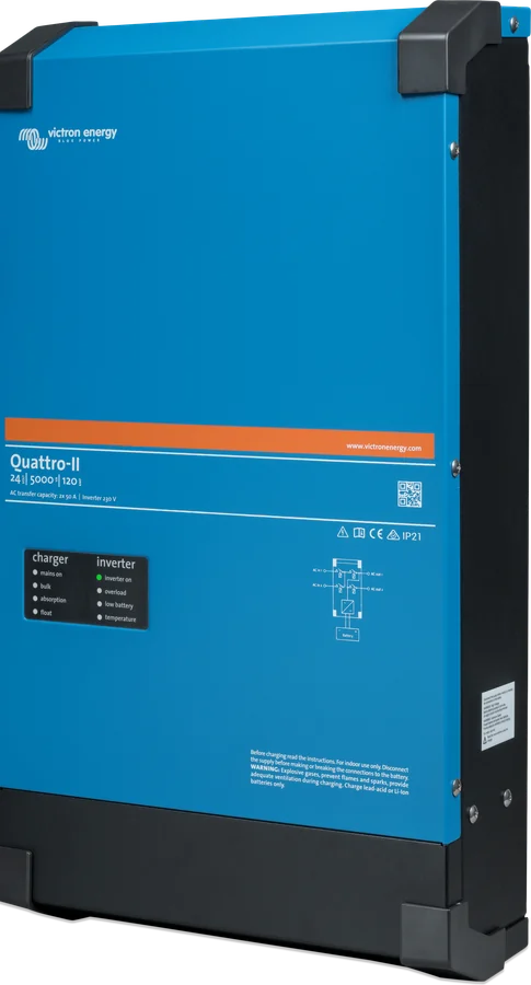
Quattro-II automatically selects the input that has voltage. When both inputs have voltage, it selects AC-in-1 — this is usually where the generator is connected, and the mains or shore power — to AC-in-2. If it “does not accept mains” while the generator is running, that is in line with this logic. Note: if AC is only present on AC-in-2, and the DC battery voltage is 10% or more below nominal (for example below 22 V for a 24 V battery), the device may not start — supply AC to AC-in-1 or charge the battery.
Does the inverter switch off under load, or is the overload LED lit? That is a different problem — see “MultiPlus reports overload”.
04When it is a hardware fault
If the voltage and frequency at the input terminals are correct, the settings have been checked, and the device still does not connect, or relay-related codes (8, 11, 24) keep recurring despite a correct installation — contact the dealer or installer. Prepare the model, serial number, firmware version, error code, installation diagram and a description of the checks you have carried out.
Devices this applies to
 MultiPlus-IIInverter/charger with UPS function: pure 230 V sine wave, PowerAssist supports a weak shore connection.
 Quattro-IIInverter/charger with two AC inputs — mains and generator without an external changeover switch.
 Cerbo GXSystem control centre and gateway to the VRM portal.
 VE.Bus Smart dongleBluetooth for a VE.Bus inverter/charger — view, switch on and set the campsite current limit on your phone, plus a battery sensor.