

Home with energy storage (ESS)
Home energy storage for a property with a three-phase supply: three MultiPlus-II 48/5000 units — one per phase — the whole house connected behind the storage system, and a Victron Lithium NG 51.2 V battery bank with Lynx Smart BMS NG. What works in a power cut, how to connect photovoltaics, which fuses and cable cross-sections — assembled from Victron instructions: ESS, MultiPlus-II, Lithium NG, Lynx Smart BMS NG and Victron system drawings.
Four decisions in the correct order
ESS (Energy Storage System) is the operating mode of Victron inverter/chargers in a grid-connected home. It stores surplus from the panels and returns it in the evening, and in a grid failure it powers the home from the battery. In a home with a three-phase supply, ESS can cover all three phases — then the whole house keeps running in a power cut. The system is chosen in this order:
- 1. Three phases, three MultiPluses. A three-phase ESS needs at least one MultiPlus on each phase — here three identical MultiPlus-II 48/5000 units on L1, L2 and L3, linked by VE.Bus in a three-phase system.
- 2. The whole house behind the storage system. All circuits, including three-phase ones, are on the AC-out-1 outputs. Between the supply and the MultiPluses there are only protections — so a grid meter is not needed.
- 3. Battery. Six Victron Lithium NG 51.2 V/100 Ah batteries — 600 Ah, about 30.7 kWh — under a Lynx Smart BMS NG 1000 A. 200 Ah per MultiPlus, as recommended in its manual.
- 4. Photovoltaics. The existing grid inverter is moved to the output — it also works in a power cut, up to 9.6 kWp with this bank. An MPPT controller on the DC side lets the system ride through longer grid outages.
Among Victron system drawings (“Manual & Drawing”) we did not find a three-phase ESS connected to the grid with Lithium NG batteries. This system combines the topology from the ESS manual (three-phase ESS, grid metering) with values from the MultiPlus-II and Lithium NG manuals, from the Lynx Smart BMS NG datasheet and from Victron system drawings: BJE-354A (three MultiPlus-II units in a three-phase arrangement with an MPPT 250/100 — this is an off-grid system with 15 kVA units, so only the three-phase principles and the PV-side values were taken from it) and BJE-367A (two MultiPlus-II 5 kVA units with Lithium NG batteries and Lynx Smart BMS NG). The design and the notification to the grid operator are carried out by an installer with the required qualifications.

Whole house in a power cut
All circuits are behind the storage system, so when the grid fails the battery powers the whole house — including three-phase loads. Each phase has 4,000 W of continuous power.
No grid meter
There are no loads or PV inverter before the MultiPluses, so the GX device calculates grid use from the MultiPluses’ own measurements.
Photovoltaics even in a power cut
The PV inverter on the output works in the local grid created by the MultiPluses. The MPPT prevents the system getting stuck if the battery is discharged.
Three phases balanced
When set to “Total of all phases”, the three MultiPluses deliver the same power — a large load on L1 is also supported by L2 and L3.
How it is connected
Three-phase ESS from the Victron manual: only protections from the supply, one MultiPlus-II 48/5000 on each phase, the whole house and the PV inverter on the outputs, a 48 V Lithium NG battery bank with Lynx Smart BMS NG, an MPPT 250/100 controller and a Cerbo GX. Hover over or tap a diagram element — we will show what it is for. This diagram is illustrative; the protections for each phase and each battery are shown in the detailed diagram below.
- Distribution board without loadsFrom the supply only protections: a main switch with surge protection and one switch up to 50 A for the input of each MultiPlus.
- Three MultiPlusesMultiPlus-II 48/5000 on L1, L2 and L3, linked by VE.Bus and configured as a three-phase system.
- The whole house behind the storage systemAll circuits, including three-phase ones, are on the AC-out-1 outputs — in a power cut the battery powers them. A grid meter is not needed.
- PhotovoltaicsThe grid inverter on the output (up to 9.6 kWp with this bank) also works in a power cut; the MPPT 250/100 charges the bank from new panels.
- 48 V bank with BMS NGSix Lithium NG 51.2 V/100 Ah batteries, each with a fuse; Lynx Smart BMS NG 1000 A and Lynx Distributor: 3 × 200 A and 125 A.
- Cerbo GXCerbo GX connects to the MultiPluses via VE.Bus, to the BMS and MPPT via VE.Can, and manages the ESS.
Distribution boards, protections and DC side
The same house phase by phase: input protections, three MultiPluses, a common output busbar, a fuse for each battery and each MultiPlus, and the PV side. The values come from the MultiPlus-II and Lithium NG manuals, the Lynx Smart BMS NG datasheet and Victron system drawings. The protections for the house circuits are selected by the designer in accordance with Polish regulations.
- InputsMain isolator with surge protection, three-phase busbar and three input breakers, each rated at no more than 50 A. Phases in L1-L2-L3 order.
- OutputsAC-out-1 from three MultiPlus units on the house distribution board busbar; circuits fitted with residual-current devices (Type A is sufficient) and MCBs.
- PV inverterOn the AC-out-1 busbar, with its own protection; up to 9.6 kWp with this battery bank.
- DC to the MultiPlus unitsThree 200 A fuses, 70 mm² cables (up to 5 m) — all the same length and cross-section. Negative cables first, then VE.Bus cables.
- 48 V battery bankSix batteries, each with a fuse on the positive in a Lynx Distributor; Lynx Smart BMS NG 1,000 A; MEGA 58 V fuses.
- PV side15 A DC switch per string, PV isolator and Type 2 surge protection matched to 250 V; MPPT with 125 A fuse.
What Victron documentation actually states
| Location | Value | Source |
|---|---|---|
| Three-phase system | star (Y), at least one MultiPlus per phase; identical units on a common battery; not for delta (Δ) configuration | MultiPlus-II and ESS manuals |
| Sequence and configuration | phases connected in L1-L2-L3 order; the three-phase system is programmed in VE.Bus Quick Configure before all other settings | drawing BJE-354A (three-phase MultiPlus-II) |
| DC cables to each MultiPlus | 70 mm² at a battery-to-MultiPlus distance of 0–5 m, 120 mm² at 5–10 m (per conductor); all the same length and cross-section | MultiPlus-II manual |
| DC fuse for each MultiPlus | 200 A; recommended battery capacity 200–800 Ah per unit | MultiPlus-II manual |
| AC input of each MultiPlus | fuse or MCB rated at no more than 50 A (5 kVA model), lower with a weaker supply; pass-through current 50 A | MultiPlus-II manual |
| AC-out-1 | RCD and protection matched to the load; Type A is sufficient; three-phase loads allowed | MultiPlus-II and ESS manuals |
| Power of one MultiPlus-II 48/5000 | 5,000 VA; continuous 4,000 W at 25 °C, 3,700 W at 40 °C, 3,000 W at 65 °C; peak 9,000 W; charging up to 70 A | MultiPlus-II manual |
| Aggregation at a single connection point | the device has fixed shutdown thresholds and cannot be combined above 30 kW at one common connection point | MultiPlus-II manual |
| Lithium NG 51.2 V/100 Ah | 5,120 Wh; charge and discharge up to 100 A continuous (1C), 200 A for 10 s; charging from +5 to +50 °C; IP65; 37 kg | Lithium NG datasheet |
| Battery fuses | each battery on the positive; value no higher than the lowest of: cable rating, battery current, system current | Lithium NG manual |
| Lynx Smart BMS NG 1,000 A | 1,000 A contactor continuous, 1,200 A for 5 minutes; AUX output 1.1 A; up to 25 51.2 V batteries (128 kWh) | Lynx Smart BMS NG and Lithium NG datasheets |
| Sum of fuses in the Lynx | no more than the current of the weakest module: 3 × 200 A + 125 A = 725 A, so the 1,000 A version | Lynx Distributor manual |
| Fuses at 48 V | MEGA 58 V version — rated voltage no lower than the system voltage | drawing BJE-354A |
| MPPT 250/100 fuse | 125 A in the Lynx Distributor | drawing BJE-354A (MPPT 250/100) |
| PV side for MPPT 250/100 | up to 5,800 W at 48 V; open-circuit voltage up to 250 V in the coldest conditions; 15 A DC switch per string, isolator and Type 2 surge protection | drawing BJE-354A (MPPT 250/100) |
| Cerbo GX | powered from the AUX of the Lynx Smart BMS NG through a 1 A fuse | drawing BJE-367A (BMS NG) |
| PV inverter on the output | factor 1.0 — PV power no greater than the inverter/charger continuous power at 25 °C; lithium battery at least 4.8 kWh per 1.5 kWp | AC coupling and the Factor 1.0 rule |
| Grid setpoint | factory default 50 W; higher in larger systems | ESS manual |
AC cable cross-sections and circuit protection for the house follow the design and Polish regulations — Victron only gives the limit values for its devices. You can calculate DC cables for the other circuits in the cable and fuse calculator.
How many batteries and what power
In a grid-connected home you do not size for the worst month, as in an off-grid cabin — the battery is there to carry the daytime surplus into the evening and keep the home running during a power cut. The ESS manual gives three rules:
- A small battery is cheaper, but it is fully used every day and charged at high currents. A large one, together with a large PV array, will store surplus energy for several cloudy days and keep the home running for longer during a power cut.
- Inverter power in a backup system is sized to the loads that must run during a power cut. Here that is the whole house: 3 × 4,000 W continuous power at 25 °C, 4,000 W per phase.
- PV inverter on the MultiPlus output requires a minimum battery capacity: for a lithium battery, 4.8 kWh for every 1.5 kWp.
The MultiPlus-II manual gives the recommended capacity for one unit: 200–800 Ah for the 48/5000 model. For three units on a common battery bank it gives no separate figure — we have adopted 3 × 200 Ah = 600 Ah, i.e. six Lithium NG 51.2 V/100 Ah batteries, about 30.7 kWh. By comparison: one MultiPlus-II 48/15000 with the same total power has a manual range of 300–1,200 Ah. Each MultiPlus has a 200 A fuse — the same as two 100 A batteries can deliver continuously.
| Month | Yield per 1 kWp | 10 kWp field per day |
|---|---|---|
| June | 4.43 kWh | approx. 44.3 kWh |
| April | 3.96 kWh | approx. 39.6 kWh |
| September | 3.49 kWh | approx. 34.9 kWh |
| October | 2.36 kWh | approx. 23.6 kWh |
| November | 1.14 kWh | approx. 11.4 kWh |
| December | 0.85 kWh | approx. 8.5 kWh |
Warsaw, field tilted at 39°, PVGIS 5.3 data (SARAH3, 2005–2023) with 14% losses. The 10 kWp field is an example: the PV inverter is on the output together with the field on MPPT. From April to September, average daily yield (34.9–44.3 kWh) exceeds the 30.7 kWh battery bank capacity — whatever the house does not use and the battery cannot store goes to the grid. In November and December (8.5–11.4 kWh per day), the battery bank will rarely fill from the panels. You can check your own city in the energy balance calculator.
Operating modes and GX device settings
ESS is configured in three steps: three-phase setup in VE.Bus Quick Configure or VE.Bus System Configurator, the grid code and ESS assistant in VEConfigure in all three MultiPlus units, and finally the GX settings in the Settings → ESS menu. The most important ones according to the ESS manual:
| Setting | What it does |
|---|---|
| Mode: Optimized (with or without BatteryLife) | Surplus from the panels goes to the battery, and when the panels cannot cover the load, the battery powers the house. BatteryLife protects the battery from staying discharged for too long; the manual recommends leaving it enabled even with lithium batteries. |
| Mode: Keep batteries charged | The battery is discharged only during a grid failure; when the grid returns, it charges from the grid and from the panels. |
| Grid metering | “Inverter/Charger” — in this setup, all loads and the PV inverter are on the MultiPlus outputs, so a grid meter is not needed. “External meter” is selected only when a grid meter is installed. |
| Minimum SoC (unless grid fails) | Below this value, ESS stops powering the house from the battery — unless the grid has failed; then it keeps discharging down to other thresholds. Example from the manual: 30% for self-consumption, 70% as reserve. |
| Multiphase regulation | “Total of all phases” (default and recommended) — the three MultiPlus units output and draw the same power, and the total of the phases tends towards zero. “Individual phase” — each phase is zeroed separately. Details in the Three phases section. |
| Feed-in excess solar charger power | The MPPT solar charge controller always works at full power, and feeds the excess into the grid. Note: the DVCC charge current limit then stops working. |
| Grid feed-in | Complete disabling or limiting of exporting energy from AC and DC PV. Export happens only when the surplus covers the loads and the battery is charged. |
| Grid setpoint | Factory setting 50 W — a small draw from the grid so the system does not export energy if it overshoots. Higher in large systems. |
| Peak shaving | PowerAssist from the battery when the loads exceed the input current limit — always, or only above Minimum SoC. Here it covers the whole house, because all circuits are on the outputs. |
| Scheduled charge levels | Up to five periods in which the system charges the battery from the grid to the set SoC — typically in the cheaper tariff period. |
The grid code is selected in VEConfigure on the Grid tab (the password is provided by the supplier) — in each of the three MultiPlus units. The ESS manual warns: if “None” is set, the system will not power the loads from the battery when the grid is present — you must set a code even if you do not intend to feed energy back. VictronConnect does not allow you to change it.
Solar PV: inverter to output, MPPT to DC
ESS works with MPPT solar charge controllers, grid-tie inverters, or both. The manual compares them like this: MPPT has up to 99% efficiency, while energy from a grid-tie inverter charging the battery passes through double DC–AC–DC conversion with losses of up to 20–30%. When energy is used mainly during the day, a grid-tie inverter is more economical.
- Grid-tie inverter on the MultiPlus outputs also works during a failure: the MultiPlus units create a local grid for it and regulate its power by shifting the frequency. The inverter must support this (island mode, micro-grid) — Victron has setup notes for, among others, Fronius, SolarEdge, SMA and ABB.
- Factor 1.0, no exceptions. PV power on the output must not be greater than the continuous power of the inverter/charger at 25 °C — here 4,000 W per phase. In addition, the minimum lithium battery capacity is 4.8 kWh per 1.5 kWp: with 30.7 kWh this gives 9.6 kWp, and that is the limit in this setup. With a field larger than the inverter, the inverter power is what counts.
- Grid export from a grid-tie inverter happens automatically. Complete no-export is only with Fronius and the Zero feed-in function; with other brands, ESS will not prevent exporting energy. Power from MPPT can be exported or not — that is a switch in GX.
- MPPT during longer outages. According to Victron, MPPT is not needed in ESS with a stable grid, but it is required in backup systems that must survive longer outages — without it, a system with only a grid-tie inverter can get stuck with a discharged battery.
If the existing inverter is larger than 9.6 kW or does not support frequency shifting, it cannot be moved to the output. It then remains before the MultiPlus units, and the system needs a grid meter — see Three phases.
When the PV inverter on the output is running at full power into a large load and that load suddenly switches off, all the power briefly goes into the battery — before the MultiPlus raises the frequency and limits the PV inverter. With a full battery, the voltage spikes, the MultiPlus may shut down with a DC overvoltage alarm, and the AC voltage spike can damage the PV inverter.
Up to 5,800 W of panels at 48 V, open-circuit voltage of the array up to 250 V in the coldest conditions. For MPPT, factor 1.0 and the minimum battery capacity do not apply; charge current is controlled by the Lynx Smart BMS NG via DVCC. String sizing: MPPT calculator.
Three phases without a grid meter
A three-phase ESS needs at least one MultiPlus on each phase. There are no loads or PV inverter before the MultiPlus units here, so a grid meter is not needed: GX calculates grid consumption from the MultiPlus measurements (Grid metering: Inverter/Charger). The ESS manual states the condition clearly — without a grid meter, all loads and PV inverters must be on the outputs.
- Identical devices. The same model and the same firmware, a common battery, DC cables of the same length and cross-section. A star (Y) arrangement — not a delta.
- Phase order. Victron drawing BJE-354A: the phases from the grid must reach the MultiPlus units in L1-L2-L3 order, otherwise the three-phase system will not work properly.
- VE.Bus. RJ45 UTP cables directly from device to device, without boxes or splitters. Connect the battery negatives first, then the VE.Bus cables. One control panel and one GX device in the system.
- Configuration. First the three-phase setup in VE.Bus Quick Configure or VE.Bus System Configurator, then VEConfigure — the ESS assistant in all units. Charge current is set per phase, not for the whole system.
- Billing. The three MultiPlus units sum energy phase by phase, while the utility meter may sum it differently — hence the differences between VRM and the bill. For billing compatibility, Victron recommends the EM24 meter (net summation) in three-phase systems instead of the ET340.
The grid meter returns to the design whenever anything is left before the MultiPlus units — a circuit, a car charger or a PV inverter. In that case a meter is installed in the main distribution board, for example VM-3P75CT, and in the GX device you set Grid metering = External meter. Problems with the meter: “VM-3P75CT meter: GX cannot see it”.
| Loads | ESS | On the meter | |
|---|---|---|---|
| L1 | 6000 W | 2000 W | 4000 W |
| L2 | 0 W | 2000 W | −2000 W |
| L3 | 0 W | 2000 W | −2000 W |
| Total | 6000 W | 6000 W | 0 W |
Example from the ESS manual for the “Total of all phases” setting: 6,000 W loads on L1 exceed that phase inverter power, so all three MultiPlus units deliver 2,000 W each, and the sum of phases on the meter is 0 W. With “Individual phase” each phase is zeroed separately — energy then flows between phases through the DC bus, with losses from double conversion.
48 V Lithium NG battery bank and its protection
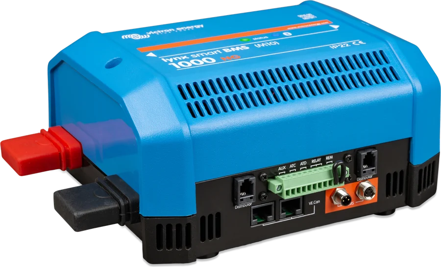
The storage consists of six Victron Lithium NG 51.2 V/100 Ah batteries connected in parallel — 48 V, 600 Ah, about 30.7 kWh. NG batteries work only with a BMS marked “NG”; here that is a Lynx Smart BMS NG 1000 A, which detects the number of batteries and how they are connected. One BMS can handle up to 25 51.2 V batteries, that is 128 kWh.
- Fuse on each battery. The Lithium NG manual: every battery connection must be protected, and in a parallel bank each battery has a fuse on the positive terminal. The rating must not exceed the lowest of three values — cable current-carrying capacity, battery current (100 A continuous) and system current. System cables are connected diagonally so the current is shared evenly.
- 1000 A BMS, not 500 A. The sum of the fuses in the Lynx system must not exceed the current of the weakest module. Three MultiPlus units at 200 A and an MPPT at 125 A give 725 A — hence the 1000 A version.
- Currents are within limits. The MultiPlus units charge at up to 3 × 70 A, and the MPPT at up to 100 A — 310 A in total, with 600 A continuous charge current for the battery bank. The BMS NG controls charging and discharging via DVCC; enabling “Feed-in excess solar charger power” disables the DVCC current limit.
- Temperature and space. Charging from +5 to +50 °C, discharging from −20 to +50 °C, IP65 enclosure. Leave 20 mm clearance on all four sides of the battery for ventilation; you may lay it on its side, but not with the terminals facing down. Mount the MultiPlus units side by side, with at least 10 cm free space below, above and beside them.
- 58 V fuse links. At 48 V, each fuse must have a rated voltage not lower than the installation voltage — DC fuse links for 12 and 24 V are not suitable, even if the current rating matches.
BMS NG thresholds: at 3.0 V per cell there is a pre-alarm, below 2.8 V the loads are disconnected, above 3.6 V or at the wrong temperature — charging ends. An additional battery monitor is not needed: the BMS NG has its own and reports battery status via VE.Can.
Whole-house loads on the outputs: RCDs and earthing
The AC-out-1 outputs of the three MultiPlus units form a three-phase bus that supplies the whole house. When the grid is present, the house is powered through the MultiPlus units (up to 50 A per phase), and in an outage from the battery: 4,000 W continuous power per phase at 25 °C, 3,700 W at 40 °C, 9,000 W peak.
- AC inputs — each through a fuse or circuit breaker rated at no more than 50 A for the 5 kVA model; for a weaker supply, proportionally lower. Set the input current limit to match the supply size. Do not swap phase and neutral.
- AC-out-1 — residual current device and protection matched to the load. The MultiPlus has a mains transformer, so there is no DC at the AC terminals — type A RCDs are sufficient. Three-phase loads, for example a heat pump, may be connected to the outputs; during an outage they load each phase.
- AC-out-2 (up to 32 A per unit) — optional for loads that should disconnect themselves during an outage, for example a water heater. It switches off immediately when operating from the battery and comes back about 2 minutes after the grid returns. Also with an RCD and circuit breaker.
- Earthing — these are Class I devices. In a fixed installation, continuous earthing of the enclosure is provided by the protective conductor of the AC input. When operating from the battery, the earth relay connects the output N to the enclosure — without this, the RCDs on the outputs would not work.
An inverter/charger connected to a battery may have dangerous voltage on the input and output terminals even when switched off. Before working on the wiring, disconnect the grid, battery and panels. The installation should be carried out by a qualified electrician.
With the grid connected, the cause is often loss of mains detection (LOM) with a weak supply — see “ESS draws power from the grid” and “MultiPlus reports overload”. Errors in a multi-unit system: VE.Bus error codes.
Grid connection in Poland
ESS always requires anti-islanding protection — even without exporting energy. Victron states that the built-in protection can be used where the device has certification for the given country; otherwise an external one is needed. In Poland, distribution system operators (DSOs) use the list of certified devices maintained by PTPiREE when connecting generation modules.
Status of the lists on 21 September 2026: in the list compliant with the “Terms and procedures for the use of certificates” version 1.2 — accepted until 31 December 2026 — the following MultiPlus-II 230V types are listed with specific firmware versions, all as type A modules. We found no Victron devices in the list compliant with version 1.3. In a three-phase system, each of the three MultiPlus units must have the same type and the same firmware version.
| MultiPlus-II 230V | Certificate 2622/0478-O-CER/E1 — firmware version | Certificate 25-414-00 — firmware version |
|---|---|---|
| 24/3000/70-32 (also GX) | 2611510 | 2611508 |
| 24/5000/120-50 | 2615510 | — |
| 48/3000/35-32 | 2629510 | 2629497 |
| 48/3000/35-32 GX | 2629510 | 2699508 |
| 48/4k5/55-32 (also GX) | — | 2601558 |
| 48/5000/70-50 | 2623510 | 2623556 |
| 48/5000/70-50 GX | 2623510 | 2623508 |
| 48/6k5/100-50 (also GX) | — | 2602558 |
| 48/8000/110-100 | 2621510,00 (listed as such) | — |
| 48/10000/140-100 | 2627510 | — |
| 48/15000/200-100 | 2619510 | — |
The certificate covers a specific firmware version, and the lists are updated. Before submitting, compare the full model type and firmware version with the current list on the PTPiREE website and check your DSO’s requirements — the final compliance check takes place at the commissioning approval stage. A storage system operating in parallel with the grid is designed and reported to the operator by a qualified installer; the grid code is set in VEConfigure.
Eight mistakes that cost the most
Victron documentation describes each of them — and every one can be avoided at the design stage.
Load before the MultiPlus units
Without a grid meter, all loads and PV inverters must be on the outputs. One circuit before the MultiPlus units — and the GX device will calculate grid import and household consumption incorrectly.
Incorrect phase order
Grid phases must reach the MultiPlus units in the L1-L2-L3 order. Otherwise the three-phase system will not work properly.
Different DC cables
The DC cables to all MultiPlus units must have the same length and cross-section — here 70 mm² at a distance of up to 5 m.
Lynx Smart BMS too small
3 × 200 A for the MultiPlus units and 125 A for the MPPT give 725 A of fuses — more than 500 A. The 1000 A version is needed.
Battery without a fuse
In a parallel bank, each Lithium NG battery has its own fuse on the positive terminal — not just the whole bank.
32 V inserts at 48 V
The fuse must have a voltage rating no lower than the installation. With a 48 V battery bank — MEGA in the 58 V version.
PV inverter too large on the output
Factor 1.0: up to 4,000 W per phase. And minimum battery bank: 4.8 kWh per 1.5 kWp — with 30.7 kWh that is 9.6 kWp.
Grid code set to “None”
The system then does not power loads from the battery when the grid is connected. The code is set in VEConfigure in each MultiPlus, even without exporting energy.
Frequently asked questions about a home energy storage system
Will my rooftop PV inverter work during a grid failure?
Yes, if it is on the output of the MultiPlus units, as in this diagram: the MultiPlus units then form a local grid, and the PV inverter keeps working and charges the battery. The conditions are factor 1.0, a sufficiently large battery bank, and an inverter that supports frequency shifting. A inverter left before the MultiPlus units switches off during a failure. An MPPT solar charge controller is needed so the system does not get stuck with a discharged battery.
Do I need a grid meter?
No, if all loads and PV inverters are on the outputs of the MultiPlus units — then the GX calculates grid import from the MultiPlus measurements (Grid metering: Inverter/Charger). A meter is needed when anything is left before the MultiPlus units. It is also worth considering if the data in VRM must match the bill — see below.
Will three-phase loads work during a failure?
Yes. The ESS manual allows three-phase loads on the outputs of a three-phase ESS, and during a failure the battery powers them. You only need to remember that each phase has 4,000 W of continuous power at 25 °C — the sum of the loads on a phase should not exceed this.
MultiPlus-II or MultiPlus-II GX?
In a three-phase system, the MultiPlus-II GX manual recommends the non-GX model with an external GX device: there can be only one GX in the system, and the units must be identical and have the same firmware. That is why there are three MultiPlus-II units and a Cerbo GX here. Both 48/5000 versions are listed by PTPiREE.
Why do a few dozen watts keep flowing from the grid?
That is the Grid setpoint — factory default 50 W. It deliberately maintains a small import so that, if the system overcompensates, it does not export energy to the grid. In large installations the manufacturer recommends a higher value.
Why do the VRM data differ from the electricity bill?
Three MultiPlus units calculate import and export separately for each phase, while the utility meter may settle the sum of all phases. The ESS manual recommends the EM24 meter in three-phase systems, which sums net energy — then in the GX you set Grid metering = External meter. Confirm the billing method with your energy supplier.
Can I use fewer batteries?
The MultiPlus-II manual recommends 200–800 Ah per 48/5000 unit — with three units that is 600 Ah. For comparison, one 48/15000 unit with the same total power has a range of 300–1,200 Ah. A smaller battery bank is a design decision: it must cover the currents (for example, four batteries provide 400 A of continuous charging and discharging against 310 A of charging from the MultiPlus units and MPPT) and it limits the PV inverter on the output — with 20.5 kWh to 6.4 kWp.
Can I use batteries from another manufacturer?
Yes, if it is on Victron’s compatibility list and has CAN communication — then the battery state is provided by its own BMS, and no extra monitor is needed. The ESS manual does not recommend standard AGM and gel batteries for daily cycling. The Lithium NG batteries in this diagram require a BMS NG.
Devices in this setup
 MultiPlus-IIInverter/charger with UPS function: pure 230 V sine wave, PowerAssist supports a weak shore connection.
 Lithium NGVictron’s new generation of LiFePO4 batteries: 12.8/25.6/51.2 V, IP65, built-in current measurement — only with BMS NG.
 Lynx Smart BMS / NGBMS with contactor and current measurement for Smart LiFePO4 or Lithium NG banks.
 Lynx DistributorModular 1000 A DC busbars: fused distribution with MEGA fuses and monitoring, battery connection, Class-T fuses.
 SmartSolar MPPT 150 and 250 V35–100 A controllers for higher panel voltages: 150 V and 250 V, Tr, MC4 and VE.Can versions.
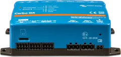 Cerbo GXSystem control centre and gateway to the VRM portal.
 GX Touch 50/70Optional 5- or 7-inch display for Cerbo GX: system overview, settings, surface or flush mounting.
What next
- ESS draws power from the grid instead of from the battery — step-by-step troubleshootingsupport
- BMS has disconnected charging or discharging — also Lithium NG with BMS NGsupport
- Energy balance calculator — panel yield for 16 Polish citiestool
- Cable and fuse calculator — cross-section for current and lengthtool
- Off-grid cabin — 48 V battery bank with Lynx Smart BMS, but no griddiagram
- VE.Bus error codes — including parallel and three-phase system faultserror codes
- GX error codes — including ESS states #1–#7error codes
Manufacturer documentation
- ESS design and installation manual — topology, design (sec. 2), GX settings with grid metering (4.3), three-phase ESS (7.3), FAQ (HTML version, status as of 22 September 2026)victronenergy.com · EN
- MultiPlus-II 230V — manual: DC cables and fuses, parallel and three-phase operation (4.5.7–4.5.8), AC wiring, ground relay, technical datavictronenergy.com · PDF · EN
- Lithium NG 12.8/25.6/51.2 V — datasheet: 51.2 V/100 Ah battery data, currents, temperatures, number of batteries per BMSvictronenergy.com · PDF · EN
- Lithium NG — manual (also covers the 51.2 V model): cable cross-sections and fuses, parallel connection, BMS wiring, installationvictronenergy.com · EN
- Lynx Smart BMS NG 500 A and 1000 A — datasheet: contactor, AUX, system example with Lynx Distributor on the battery sidevictronenergy.com · PDF · EN
- AC-coupling and the Factor 1.0 rule — PV inverter on the output, minimum battery capacity, MPPT requirementvictronenergy.com · EN
- Manual & Drawing BJE-354A (three MultiPlus-II 15 kVA in a three-phase system, MPPT 250/100, off-grid system) — source of the three-phase rules, PV-side protection, MPPT fuse and 58 V insertsvictronenergy.com · PDF · EN
- Drawing BJE-367A (two MultiPlus-II 5 kVA, Lithium NG, Lynx Smart BMS NG) — cables to the MultiPlus units of equal length, Cerbo supply fusevictronenergy.com · PDF · EN
- PTPiREE — list of certified devices (NC RfG), versions 1.2 and 1.3 from 21 September 2026ptpiree.pl · PL
- PVGIS 5.3 (JRC, European Commission) — solar irradiation data used in the yield tableec.europa.eu
Content checked against Victron Energy documentation (datasheets and manuals) — as of 22 September 2026. Report a content error · Revision log