

01Why you need an RCD and when it trips
A residual current device (RCD) compares the current in the live and neutral conductors. A difference means current is leaking to earth — for example through a person — and the RCD disconnects the circuit. It reacts to currents of around 5–30 mA, far smaller than needed to blow a fuse, and should trip within 25–40 ms. According to Victron, an RCD is mandatory in every AC installation.
Condition: leakage can be detected only when the neutral conductor is connected to earth (TN and TT systems). In an isolated system (IT), an RCD has nothing to detect.
02Where to fit the RCD
- Fit the RCD before the loads — before the installation is split into circuits.
- With an inverter or inverter/charger, the RCD must be after it (on its output) — otherwise there is no leakage protection when the inverter is running.
- Loads powered only when an external source is connected (for example AC-out-2 on a MultiPlus) need their own RCD.
On Victron’s official diagrams, each AC output (AC-out-1 and AC-out-2) has its own RCD with an MCB or a combined breaker (RCBO) — see campervan, yacht, off-grid cabin.
03N–PE connection and earth relay
Every AC source must have the neutral conductor connected to earth so the RCD can work. In the mains supply, this is provided by the supply distribution board; with a generator or a standard inverter, check before installation whether the neutral conductor is connected to earth, and if not — make a permanent N–PE connection.
An inverter/charger has two states, so Victron uses an internal earth relay:
| State | AC input relay | Earth relay | Who provides the N–PE connection |
|---|---|---|---|
| Supply from mains or generator (pass-through, charging) | closed | open | power source (mains, generator) |
| Inverter operation (no external supply) | open | closed | inverter/charger — internally |
The relay can be disabled in the settings on most models — in that case, the N–PE link must be made permanently in the installation. Where regulations do not allow the neutral conductor to be interrupted, devices “-II” (MultiPlus-II, Quattro-II) use the grid code with an externally bonded neutral path. A failed test of this relay in the MultiPlus-II is VE.Bus error 8.
Standard Victron inverters: in models from 1600 VA upwards and in the Inverter Compact 1200 VA, the output neutral is connected to the enclosure, so earthing the enclosure also earths N. If there is no reliable earthing and/or no RCD (RCCB, RCBO or GFCI) is installed, the N–enclosure link should be removed for safety; Victron warns that such an installation probably does not comply with local regulations. In smaller inverters, N is usually not connected to the enclosure, but such a connection can be made — the manual for the relevant model describes this.
04Campervan, vehicle, boat
A mobile installation has no dedicated earth electrode. All accessible metal parts — chassis or hull, pipes, engine, protective contacts in sockets — are bonded together to form a local “earth”. At a shore connection, it is not always known whether the protective conductor is connected, and phase and neutral may be swapped.
- Isolated system (IT): when the only source is an inverter or a generator without an N–PE link, touching one conductor does not complete the circuit through earth. Touching phase and neutral at the same time is always dangerous.
- Changing from TT to IT — avoid this. After disconnection from the grid, the installation loses the N–PE bond from the grid and becomes “floating”: the RCD is fitted, but it will not detect leakage. Victron recommends that even after disconnection from the grid, the installation should behave like a TT system — the N–PE link must appear automatically (earth relay in an inverter/charger or a bond in the source changeover switch).
- The TEST button on an RCD checks only the device itself (the internal test circuit simulates leakage). If there is no N–PE link, the test will “pass” even though the RCD will not trip in a real earth fault.
05DC-side earthing
- The enclosure of the inverter or MultiPlus/Quattro must be earthed (there is basic insulation between the AC circuits and the enclosure). The same applies to the enclosure of the MPPT solar charge controller.
- DC earthing is done at the battery — this should be the most reliable and most visible connection. The DC earth conductor must carry at least the short-circuit current equal to the DC fuse current; on the AC side — at least the AC protection current.
- Do not earth the positive or negative of the PV array — the PV negative of the MPPT charge controller is not isolated from the output negative, so stray currents will flow. The panel frames may be earthed (preferably to a central point) — this provides some lightning protection.
- In systems with a generator, use a single earthing point at the battery; a large generator is earthed directly at the central point.
- In Victron drawings for vehicles and boats, the MultiPlus enclosure is connected to the central negative busbar with a conductor one size smaller than the total cross-section of its negative conductors (ABYC rule).
06Boat: galvanic corrosion
When a boat is connected to shore power, the protective conductor bonds the hull to the shore earth and completes the hull–water–shore circuit. The natural potential difference between metals (0.1–1 V DC) then creates a galvanic current that slowly destroys the weakest metal: the hull (especially aluminium), propeller, shaft. Disconnecting the protective conductor from the hull is not a solution — the RCD then does not work reliably. Safe methods:
| Solution | How it works | Notes |
|---|---|---|
| Galvanic isolator | Two diodes connected in anti-parallel in the protective conductor; they conduct only above about 1.4 V DC, so they block galvanic current but pass AC earth-fault current. | Small and light, but it relies on a good shore protective conductor; galvanic current can also flow through the neutral conductor if any device bonds N to earth. |
| Isolation transformer | Completely isolates the input from the output; on the boat side, one of the output conductors is bonded to the hull, creating its own N and PE. | According to Victron, this is the better solution: safety like at home, isolation from faults on neighbouring boats, and often the option to switch between 230/120 V. |
Protective anodes protect against corrosion between the boat’s own metals — they only delay it and must be checked regularly.
Victron states that earthing and protection requirements vary between countries and applications. In Poland, AC installations are carried out and inspected by a person with electrical qualifications.
Devices in this guide
 MultiPlusInverter/charger 800 VA–20 kW: PowerAssist, UPS under 20 ms, parallel and three-phase operation.
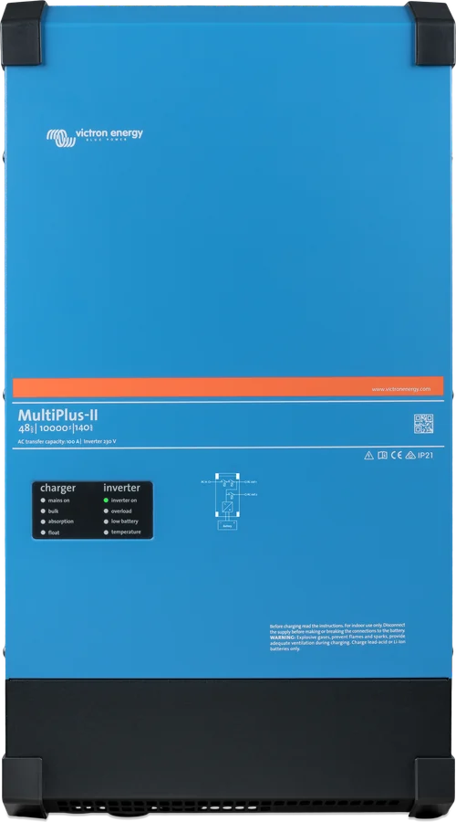
 MultiPlus-IIInverter/charger with UPS function: pure 230 V sine wave, PowerAssist supports a weak shore connection.
 Quattro-IIInverter/charger with two AC inputs — mains and generator without an external changeover switch.
 SmartSolar MPPT 75/10–100/20Small solar controllers with Bluetooth for campervans, boats and cabins.