
01Before you start
- Update: for a first installation and when problems occur, the manufacturer recommends updating the firmware of all VE.Bus devices and the GX device.
- System restart: switch off all devices one by one, then switch them back on — using the On / Off / Charger-only switch on the front panel.
- Cables: use the factory network cables. Self-crimped RJ45 cables are a known cause of many of the errors on this list.
- Where you will see the code: this depends on the fault: in the GX device and the VRM portal, in VictronConnect, and on the device LEDs (how to read them — see MultiPlus-II LED decoder). Note: error 17 in systems with multiple units per phase may be shown on the device LEDs, not in VRM or on GX.
The manufacturer notes that the steps described are intended for trained professionals, and that some settings and updates require experience.
02VE.Bus codes
Device switched off because another phase in the system switched off
One phase in the multi-phase system has failed — most often because of a low battery voltage alarm, overload or temperature. The other phases then show code 1.
Find the phase that does NOT show code 1, and check its LEDs to determine the cause (usually overload, low battery voltage or temperature). Because of the automatic restart, you need to look at the LEDs while the problem is still present and the system is off.
The GX device and VRM portal show code 1 and the alarm status of each phase. In VRM, enable automatic alarm monitoring — then you will see overload and temperature alarms from the same time in the log.
Clears automaticallyonce the cause has been removed.
Original: “Device is switched off because one of the other phases in the system has switched off” · Victron source
Mixed old and new MK2 protocol
This should not happen — contact service through your dealer.
Clears automaticallyonce the cause has been removed.
Original: “New and old type MK2 protocol mixed in the system” · Victron source
Not all, or too many, devices found in the system
Often appears after error 1 — if so, remove the cause of error 1.
System configured incorrectly: all devices on the VE.Bus must be configured as one system (parallel, split-phase or three-phase). Do not combine two separate VE.Bus systems.
Faulty communication cable: use factory cables, not self-crimped ones — VE.Bus is very sensitive to wiring faults.
Blown DC fuse in one of the devices: when mains is available everything looks fine, but when mains fails the device with no DC supply “disappears” from the system.
Clears automaticallyonce the cause has been removed.
Original: “Not all, or more than, the expected devices were found in the system” · Victron source
No other devices found
The master device is configured for parallel or multi-phase operation, but it cannot see any other devices on the bus.
It may appear briefly when the system is restarted after a fault — in that case it is not a real error. Otherwise, check the communication cables (do not use self-crimped cables).
Clears automaticallyonce the cause has been removed.
Original: “No other device found” · Victron source
Overvoltage on AC output
This can happen when the AC wiring of one of the slave devices is connected incorrectly or not connected at all. Check the AC wiring.
Clears automaticallyonce the cause has been removed.
Original: “Overvoltage on AC out” · Victron source
Error in DDC programme (Assistant)
Error in the Assistant. Update the VE.Bus firmware in all devices, download the latest VEConfigure with the current Assistants, and configure the system again.
In newer firmware, the error also appears when a VE.Bus BMS is connected (or disconnected) and the Assistant is not configured correctly.
Clears automaticallyonce the cause has been removed.
Original: “Error in DDC Program” · Victron source
External device connected — Assistant required
An external device has been connected (for example, a VE.Bus BMS), but the Assistant that supports it has not been loaded. Configure the Multi/Quattro with the appropriate Assistant.
Clears automaticallyonce the cause has been removed.
Original: “External device connected, assistant required” · Victron source
Ground relay test failed
This error means the ground relay test failed in a MultiPlus-II or EasySolar-II. In the first hardware version, the measurement also includes externally connected ground relays, while in newer versions only the internal relay is checked. In inverter mode, with no mains, the relay is continuously checked as closed; when switching to mains, it is checked whether it opens. The tests are always carried out, except in systems where the relay has been disabled in VEConfigure.
Details (GND Relay Error, PE2 Open, PE2 Closed) are shown in the GX device. Errors are stored in the device memory and may be old — note the counters, start the system, and compare them after the next shutdown.
The diagnosis method depends on the hardware version (changeover around 2020/2021). The older version applies, among others, to: MultiPlus-II 48V 3kVA up to serial number HQ2048, 48V 3kVA GX up to HQ2050, 24V 3kVA up to HQ2101, 48V 5kVA up to HQ2116, 48V 5kVA GX up to HQ2122, EasySolar-II 48V 3kVA MPPT 250-70 GX up to HQ2130; the remaining models and serial numbers — new version.
New version: if the device repeatedly reports a ground relay error, the relay is probably faulty and needs replacing.
Old version — possible causes: the output neutral conductor connected to earth outside the device (correct the wiring); input neutral connected to output neutral without this configuration in the software (remove the connection or — only where required by regulations — select the correct grid code); leakage or short circuit in the loads (disconnect circuits and check them one by one — the test is performed when switching to mains); faulty relay or its measurement circuit (configure each device separately and check whether it switches without an error); in three-phase systems — mismatch of loads with the safety circuit (contact your dealer).
Original: “Ground relay test failed” · Victron source
System time synchronisation problem
This usually appears when the system is restarted and is not then a real error. A real cause is often a previous error 1 (for example, one phase switched off with the switch). Remote VEConfigure can also trigger a restart.
Another possibility: a blown DC fuse in one of the devices — when mains fails, the device with no supply disconnects from the system.
Clears automaticallyonce the cause has been removed.
Original: “System time synchronisation problem” · Victron source
Relay test fault (installation or relay)
Failed autotest of the relays in MultiPlus-II or EasySolar-II. This is often due to an installation error, and less often to a fault. When a grid code is selected, the relays are tested before every grid connection.
Step 1: update the software. Step 2: check that the wiring matches the installation and local regulations, including earthing on the AC input — do not connect earth to neutral in the unit itself (danger and possible RCD failure). Step 3: disconnect L and N from the AC out terminals of each unit — if the system then starts, the problem is in the load (for example leakage between neutral and earth). Step 4: check the output neutral conductor — usually there must be no external connection between input N and output N, or to earth; local regulations may be an exception, for example Australia AS4777.2:2015. In that case, select the correct grid code configuration (MultiPlus-II with firmware 466 or later) and after configuration carry out the standard safety tests in both modes, including the RCD test with the AC input connected and disconnected. Step 5: the live and neutral conductors on the input may be swapped (it will show “Failing step: 8”).
With software from 454 and Venus OS from v2.23, the GX device shows a detailed error report 11 (MultiPlus → Alarm Status → VE.Bus Error 11 report). If the fault remains after all steps, the unit may be faulty — report it to the dealer with the full installation diagram and a description of the tests performed.
Clears automaticallyonce the cause has been removed.
Originally: “Relay Test Fault - Installation error or possibly relay failure” · Victron source
Config mismatch with 2nd microcontroller
Some devices, such as MultiPlus-II, have two microcontrollers and some settings must be stored in both. Connect the unit to VEConfigure 3, check the settings and send them with “all settings” (not “modified settings”).
Clears automaticallyonce the cause has been removed.
Originally: “Config mismatch with 2nd mcu” · Victron source
Device cannot transmit data
Most likely a short circuit in the communication cables. Very rarely, a faulty component on the board (in which case it must be repaired in service).
Clears automaticallyonce the cause has been removed.
Originally: “Device cannot transmit data” · Victron source
VE.Bus combination error
An incompatible combination of VE.Bus products, firmware versions or commands — for example an Interface-1140 with old firmware alongside new Multi firmware, external BMS commands with a VE.Bus BMS connected, incompatible firmware versions (updating usually helps).
Clears automaticallyonce the cause has been removed.
Originally: “VE.Bus combination error” · Victron source
VE.Bus dongle is missing
Update the software to the latest version — VE.Bus dongles are no longer needed.
This does not clear itselfthe system remains off until restarted.
Originally: “VE.Bus dongle is missing” · Victron source
Phase master missing
Only slave units show this when they have lost communication with the phase master. This applies only to systems with several units per phase.
It may appear briefly while saving configuration through remote VEConfigure — in that case, ignore it. The most common cause is the VE.Bus network cables and sockets — check the RJ45 sockets in the units, and replace all cables, including the one to the GX device. Other causes: a blown DC fuse in one of the units; out-of-date firmware in the units, Assistants and GX device.
Clears automaticallyonce the cause has been removed.
Originally: “Phase master missing” · Victron source
AC voltage at the output of a switched-off slave unit
Check that the AC wires have not been swapped — there must never be voltage at the AC output of a switched-off unit.
This does not clear itselfthe system remains off until restarted.
Originally: “AC Over-voltage on the output of a slave while switched off” · Victron source
Slave does not have AC input
Typical cause: a system with several synchronised units, but AC supply (for example from a generator) was connected to only one. Connect AC to all units, or in VE.Bus System Configurator disable “Switch as Group” (not available in an ESS system).
This does not clear itselfthe system remains off until restarted.
Originally: “Slave does not have AC input!” · Victron source
Configuration mismatch
Advanced VE.Bus options are not allowed when a grid code is selected.
This does not clear itselfthe system remains off until restarted.
Originally: “Configuration mismatch” · Victron source
This device cannot function as a slave
This is an obsolete, unsuitable model — it must be replaced.
This does not clear itselfthe system remains off until restarted.
Originally: “This device cannot function as a slave” · Victron source
Switch-over system protection initiated
The unit detected current flowing through the back-feed relay, which should be open. Possible causes in order of likelihood: (MultiPlus-II with external current sensor only) the “External current sensor connected” option was not ticked in VEConfigure; AC load too high at the moment the relay disconnected (reduce the load, check the permitted switch current in the datasheet); slow input voltage drop, typical with generators — raise the lower AC input voltage threshold in VEConfigure, for example to 210 V (factory setting 180 V); faulty relay or current-sensing circuit (replace the unit).
In systems with several units, the fault appears on all units at once. The manufacturer describes a procedure for finding the faulty unit by measuring the resistance between the AC input and output terminals after disconnecting the wiring — this is work for a qualified installer. If you carry out this procedure, do it immediately after the fault occurs and do not reset the system; first note the LED codes, then completely disconnect the incoming and outgoing AC wiring on all units before measuring.
This does not clear itselfthe system remains off until restarted.
Originally: “Switch-over system protection initiated” · Victron source
Incompatible VE.Bus configuration
Units with different firmware were used (update all to the same version) or units that are incompatible with each other: the 4-digit number in the compatibility identifier (on the label, for example 2623_B) must be identical in all units in the system, and units on one phase must have the same letter.
This does not clear itselfthe system remains off until correctly configured and restarted.
Originally: “Incompatible VE.Bus configuration” · Victron source
Internal error
This should not happen. Switch all units off and on again — operation will resume. If the problem repeats, report it through the dealer.
This does not clear itselfthe system remains off until restarted.
Originally: “Internal error” · Victron source
“Ghost errors” (30 and 31)
Codes outside the list, caused by a corrupted message on the VE.Bus. The cause may be RJ45 cables or their connections — the manufacturer refers to the guide on VE.Bus bus interference.
Originally: “Ghost errors” · Victron source
Grid connection blocked by failed relay test
When a grid code is selected in VEConfigure, the Quattro-II tests the transfer relays before every connection to the grid and repeats the test until it succeeds. Error 128 means the test has been failing for more than 5 minutes and the unit cannot connect to the grid.
Original: “Connect prevented by failing relay test” · Victron source
Devices this applies to
 MultiPlus-IIInverter/charger with UPS function: pure 230 V sine wave, PowerAssist supports a weak shore connection.
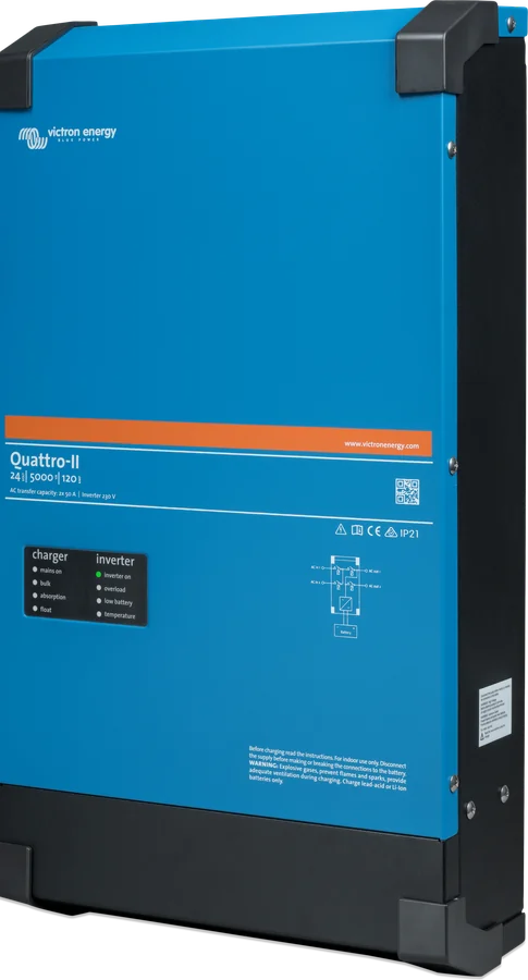
 Quattro-IIInverter/charger with two AC inputs — mains and generator without an external changeover switch.
 MultiPlusInverter/charger 800 VA–20 kW: PowerAssist, UPS under 20 ms, parallel and three-phase operation.
 EasySolar-II GXMultiPlus-II, 250 V MPPT controller and GX device factory-connected in one enclosure — 3 or 5 kVA.
 MultiPlus-II GXMultiPlus-II with built-in GX device, display and Wi-Fi — VRM without a separate Cerbo.
What next
Does the MultiPlus or Quattro not switch to the grid or generator? See the diagnostics “MultiPlus does not accept the grid”. Is the overload LED lit or flashing? See “MultiPlus reports overload”. If the manufacturer indicates a hardware fault, contact the dealer or installer from whom you bought the unit.