

01First check
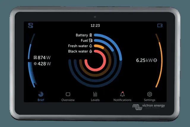
- ESS status code in the GX overview or in VRM, next to the charging state: #1 low SoC, #2 BatteryLife active, #3 and #4 BMS has blocked charging or discharging, #5 slow charging (part of BatteryLife), #6 and #7 zero charge or discharge limit set. Description of each: ESS states.
- VE.Bus status — if it is “Passthru”, the system is not using the battery; the manual treats this as a problem to be investigated (step 6).
- Software — the “Troubleshooting” chapter starts by checking that all devices have the latest software; when asking the dealer, provide the exact versions. See firmware update.
- Battery — according to the same chapter, the lead-acid battery may not be suitable for ESS and may already be worn out from heavy cycling. The manual instructs you to replace an unknown or unsupported battery with a supported type if it communicates over CAN-bus.
- GX error codes — for example #49 (grid meter not found) or #48 (DVCC with incompatible software); inverter codes — VE.Bus.
The manual prohibits using ESS in a vehicle or on a boat: after you unplug the shore power lead, the system detects grid loss for a few seconds and opens the transfer relay, and during that time there is 230 V on the plug contacts. The same applies to any lead with a plug that the user can unplug.
02Step-by-step diagnosis
1Is the switch on the unit in the On position?
In the “Charger only” position, the inverter/charger does not discharge the battery. You cannot see the switch status in VRM or on the GX device — you have to check it on site. On the MultiPlus-II, the switch is on the bottom of the unit and must be in position I, not II.
Go to step 2.
Move the switch to On (on the MultiPlus-II — position I).
2Has the SoC not dropped to the set limit?
When mains is available, ESS stops discharging the battery when SoC falls to the Minimum SoC set in the ESS menu. Example from the manual: at 60%, the 60–100% range is used for self-consumption, and 0–60% — for a mains failure. When mains fails, in inverter mode, the battery keeps discharging until other thresholds operate.
- BatteryLife (code #2) can raise this limit every day — in poor sunlight by 5% per day, until the energy taken from the battery over 24 hours matches the energy replenished. As solar input increases, the limit returns to the set value day by day.
- Discharge is allowed again when SoC rises by at least 3% above the set limit.
- The limit also works according to battery voltage (Dynamic cut-off) and BMS signals — not only according to SoC.
This is normal ESS operation. If you want to use more of the battery, change Minimum SoC (and, if applicable, the BatteryLife mode) — remember that a lower limit means less reserve for a mains failure.
Go to step 3.
3Has the battery BMS blocked discharge?
This applies to batteries with CAN-bus communication. On the GX device, open the battery in the device list, then the Parameters submenu, and check Discharge Current Limit (DCL). A value of zero means the battery does not allow the system to discharge it further (in the GX overview — code #4).
The cause lies with the battery or BMS — see “The BMS has stopped charging” and your battery’s error codes.
Go to step 4.
4Is the ESS relay test complete?
Before the inverter/charger in an ESS system starts using the battery, it must perform a relay test — for about a minute it then operates as an inverter and needs stored energy in the battery for this. If the battery voltage is too low when connecting to mains, the system starts in passthru or charging mode and waits for the battery to be charged. Until then, it does not convert direct current to alternating current: it does not power loads from the battery, does not pass energy from MPPT solar charge controllers to them, and does not export surplus from the panels to mains.
The test will run when battery voltage exceeds 14 V, 28 V or 56 V (for 12, 24 and 48 V systems) or when SoC exceeds 20%. You can check the status on the GX device: device list → Multi/Quattro → Advanced submenu → ESS Relay test — “Pending” or “Completed”. This item is visible only in systems with the ESS assistant.
Go to step 5.
Charge the battery above the stated voltage or 20% SoC — the test will run automatically.
5Is the grid code not blocking operation via the AUX input?
Some grid codes (for example German or Australian) use the AUX1 input to disable export. If AUX1 is connected to something else — for example an AC sensor or BMS — it may block system operation in this way. The manual’s solution: untick this option in the grid code settings (VEConfigure). The manual also lists grid codes that require discharge permission via the AUX inputs — compare the set code with the signals actually applied to the unit’s AUX inputs.
6Is the VE.Bus status “Passthru”?
According to the ESS manual, the system enters passthru mode when:
- the GX device has stopped receiving data from the grid meter — this applies to systems configured with an external meter (Settings → ESS → Control without grid-meter); see also error GX #49;
- in a system with a lithium battery on CAN-bus, the GX device has stopped receiving information from the battery;
- charging is not allowed (maximum charge current from the BMS = 0 A or maximum charge power = 0 W), and there is surplus energy from the panels;
- discharging is not allowed (BMS: DCL = 0 or SoC below Minimum SoC), and the loads on the AC output require more than the input current limit allows;
- the grid code requires discharge permission via the AUX inputs (step 5);
- loss of mains detection (LOM) is causing problems — often with a supply that has high impedance (step 7).
7Does the system shut down “due to overload” even though it is connected to mains?
The manual points to Loss of Mains (LOM) detection, linked to the country code set in VEConfigure. This happens when the AC input supply is “weak”, meaning the connection to mains has higher impedance than usual — for example a generator, or an old or remote house connected by a long or too-thin cable. The Victron document “VEConfigure: grid codes & loss of mains detection” describes the solutions and configuration options. If none of the steps helps, the manual advises temporarily disabling LOM to rule out this cause.
8Does the battery discharge first, then charge from mains at night?
In Optimized mode, ESS charges the battery from mains only in situations that protect it from damage:
- Sustain — switches on only after the battery is considered discharged (voltage below Dynamic cut-off or a low cell voltage signal from the VE.Bus BMS). The system then maintains the Sustain voltage — in a 12 V system: 12.5 V for lithium batteries, and for others 11.5 V for the first 24 hours, then 12.5 V — charging from mains at a maximum of 5 A per device (regardless of system voltage). The mode ends when the panels raise the voltage by 0.1 V above the Sustain level (0.2 V at 24 V, 0.4 V at 48 V).
- BatteryLife slow charge (code #5).
- Auto-recharge — when SoC falls by 5% or more below Minimum SoC, the system charges the battery from mains up to the Minimum SoC level.
What the manual says to do: increase Minimum SoC, for example by 5%, and observe what happens. You can also lower the Sustain voltages in VEConfigure, but be careful — especially with lead-acid batteries, because the Sustain levels protect them from premature damage.
9Do the panels not power the loads even though the sun is shining?
The sequence from the “Troubleshooting” chapter:
- check the “#” status codes in the GX overview;
- check the cabling — a large voltage drop between the MPPT solar charge controller and the inverter/charger prevents effective supply of AC loads from the panels;
- check operation with SVS (shared voltage sense) enabled and disabled — leave it disabled;
- check the MPPT solar charge controller charge current limit (CCL) when the panels are only lightly loaded — it should always be high, even with a full battery, unless temperature is limiting it;
- check the MPPT charge voltage setpoint (Charge Voltage Setpoint) — it should be higher than the current battery voltage. The software calculates both of these last parameters from values sent by the lithium battery over the CAN-bus; you cannot set them manually, but they help you understand what is happening.
In Keep batteries charged mode, when the battery is full, the MPPT solar charge controller may produce less — when DVCC is disabled and “Feed-in excess solar charger power” is disabled. Workarounds from the manual: enable DVCC (if the GX device manual for that battery allows it) or set Optimized mode with Minimum SoC 100% — but then, if mains fails, the system will not charge the battery from mains.
10Panels’ surplus is not fed into the grid?
- Feed-in excess solar charger power — for panels connected through MPPT controllers (DC), this setting must be On. The controller then always runs at full power: it first supplies the loads, then charges the battery, and sends the rest to the grid. Manual note: the DVCC charge current limit then stops working — with a small battery, set a safe limit in the controllers themselves.
- Grid feed-in — in this menu you can completely disable or limit feeding energy from AC and DC solar panels back to the grid. Feed-in only happens when the surplus fully covers the loads and the battery is charged (or charging at the maximum permitted current). The “Feed-in limiting active” indicator shows “Yes” only when the limit is currently active.
- Feed-in is also blocked by an unfinished relay test (step 4) and by the grid code using the AUX1 input (step 5).
03Not a fault
The ESS manual describes several behaviours that look like a problem, but are normal:
- The system is connected to the grid at all times, even with a full battery — in Optimized mode this is intentional: the grid provides more stable supply than the inverter (without flicker and shutdowns with heavy loads), and grid consumption is then negligible.
- Constant small grid consumption — the Grid setpoint setting (factory default 50 W) deliberately maintains a small import so that, if the system overshoots, it does not feed energy back to the grid. In large installations the manufacturer recommends a higher value.
- AC input current varies strongly and can even be negative (Optimized mode without feed-in) — this is the RMS current, which at power close to 0 W is high because of the interference suppression capacitors in the device. Look at the input power — it is more stable and shows the actual energy flow better.
- Charge state Bulk, Absorption or Float during discharge — with mains connected this is normal; the MPPT controllers show the “ESS” state because they are controlled by the inverter/charger via the GX device. The actual system state is shown by the VE.Bus state.
- VRM data differ from the electricity bill (two- and three-phase systems) — with an ET340 meter or without a meter, import and export are calculated separately for each phase, while many utility meters settle the net sum across all phases. This does not apply to the EM24 meter.
Typical installation diagram: house with ESS. The inverter shuts down under load with no mains connected — see “MultiPlus reports overload”.
04When it is a hardware fault
If the software is up to date, the battery is supported, the settings have been checked according to the steps above, and the system still does not use the battery or feed in surplus — contact your installer or supplier. Prepare the exact software versions of all devices (the manual asks for them with every question), the battery model and type, status and error codes, screenshots of the ESS settings, and the link to the installation in VRM.
Devices this applies to
 MultiPlus-IIInverter/charger with UPS function: pure 230 V sine wave, PowerAssist supports a weak shore connection.
 MultiPlus-II GXMultiPlus-II with built-in GX device, display and Wi-Fi — VRM without a separate Cerbo.
 Quattro-IIInverter/charger with two AC inputs — mains and generator without an external changeover switch.
 EasySolar-II GXMultiPlus-II, 250 V MPPT controller and GX device factory-connected in one enclosure — 3 or 5 kVA.
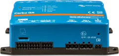 Cerbo GXSystem control centre and gateway to the VRM portal.
 Energy Meter VM-3P75CTEnergy meter for ESS and AC circuit measurement: 3 x 75 A current transformers included, VE.Can and Ethernet, refresh every 100 ms.
Sources
- ESS design and installation manual — chap. 10 FAQ (Q1–Q14) (HTML version, status as of 21 September 2026)victronenergy.com · EN
- ESS design and installation manual — chap. 11 Troubleshootingvictronenergy.com · EN
- ESS design and installation manual — chap. 4: Minimum SoC, Grid setpoint, Grid feed-in, Feed-in excess solar charger powervictronenergy.com · EN
- ESS design and installation manual — chap. 6: depth of discharge, BatteryLife, Sustain, status codes #1–#7victronenergy.com · EN