
01Why cross-section matters
A cable has resistance, so when current flows it heats up and causes voltage drop. Example from the manual: a 2400 W inverter at 12 V draws about 200 A. Two 16 mm² cables at 1.5 m each (about 1.6 mΩ each) give a voltage drop of 0.32 V on each cable, 0.64 V in total. The inverter gets 11.36 V instead of 12 V, current rises to about 210 A, and 5% of the energy is turned into heat.
Victron’s effects of excessive voltage drop: faster battery discharge, blown fuses, premature overloads and low-voltage inverter alarms, undercharged batteries, cable heating (in extreme cases fire) and shorter device life.
How much can you lose? Victron recommends that voltage drop on DC cables should not exceed 2.5% (12 V: 0.3 V, 24 V: 0.6 V, 48 V: 1.2 V). The same 2400 W inverter at 24 V draws 100 A (0.32 V drop = 1.3%), and at 48 V — 50 A (0.16 V = 0.3%). Hence the recommended maximum inverter power for system voltages: 12 V — up to 3000 VA, 24 V — up to 5000 VA, 48 V — from 5000 VA.
02Cross-section table
Maximum current for a voltage drop of 0.259 V. Length is the total length of the positive and negative cable; losses at connections are not included.
| Cross-section | up to 5 m | up to 10 m | up to 15 m | up to 20 m |
|---|---|---|---|---|
| 1.5 mm² | 4.5 A | 2.3 A | 1.5 A | 1.1 A |
| 2.5 mm² | 7.5 A | 3.8 A | 2.5 A | 1.9 A |
| 4 mm² | 12 A | 6 A | 4 A | 3 A |
| 6 mm² | 18 A | 9 A | 6 A | 5 A |
| 10 mm² | 30 A | 15 A | 10 A | 8 A |
| 16 mm² | 48 A | 24 A | 16 A | 12 A |
| 25 mm² | 75 A | 38 A | 25 A | 19 A |
| 35 mm² | 105 A | 53 A | 35 A | 26 A |
| 50 mm² | 150 A | 75 A | 50 A | 38 A |
| 70 mm² | 210 A | 105 A | 70 A | 53 A |
| 95 mm² | 285 A | 143 A | 95 A | 71 A |
| 120 mm² | 360 A | 180 A | 120 A | 90 A |
Rule of thumb for cables up to 5 m: cross-section in mm² ≈ current in A divided by 3. At 200 A: 200 / 3 ≈ 66 mm² (that is, 70 mm² in practice). The cable and fuse calculator will calculate the exact value for your length, voltage and current.
03What cables to use and how to route them
- Flexible, fine-stranded cables. Do not use rigid cables, thick-stranded cables or AC installation cable. In damp environments and on boats — “marine” cables with tinned conductors.
- Check the conductor cross-section, not the insulation thickness — some cables have very thick insulation and look thicker than they are.
- Two cables instead of one thick one are allowed if their total cross-section equals the recommended value (2 × 35 mm² = 70 mm²). Larger Victron inverter/chargers have two positive and two negative terminals precisely for this reason. Note: local regulations may require a separate fuse on each cable or each cable to carry the full load.
- As short as possible — keep the batteries close to the inverter. But do not mount electronics directly above lead-acid batteries, even sealed ones.
- Cables heat up: at a 2.5% voltage drop, 25 W of every 1,000 W of transmitted power is turned into heat. In a closed duct the heat has nowhere to go — you need a larger cross-section (even double it) or an open-top trunking.
- Slack and strain relief — in vehicles, taut cables and vibration loosen terminals and posts; support heavy cables with brackets so they do not hang from the terminals.
- Busbar — its cross-section is calculated like a cable cross-section (a 10 × 5 mm busbar = 50 mm² ≈ 150 A up to 5 m). The connection between the battery and the distribution point must have a cross-section equal to the sum of the branch cross-sections. Cover uninsulated busbars.
04Connections and terminals
- Ring terminals matched to the cable cross-section, crimped with the correct crimping tool. Tighten only with insulated tools; an accidental battery short can melt an uninsulated spanner or cause a spark and battery explosion. On the bolt, in order: the lug sits flat against the contact surface, then the washer, spring washer and nut. Do not place anything (washers, fuses) between the lug and the contact surface.
- Tightening torque from the device manual — overtightening also causes damage.
- Ferrules for screw terminals — crimped, not just pushed on.
- Insulated crimp terminals: red 0.5–1.5 mm², blue 1.5–2.5 mm², yellow 2.5–6 mm²; crimped with a ratchet crimping tool. Victron advises against bullet and butt connectors — they often give a poor contact.
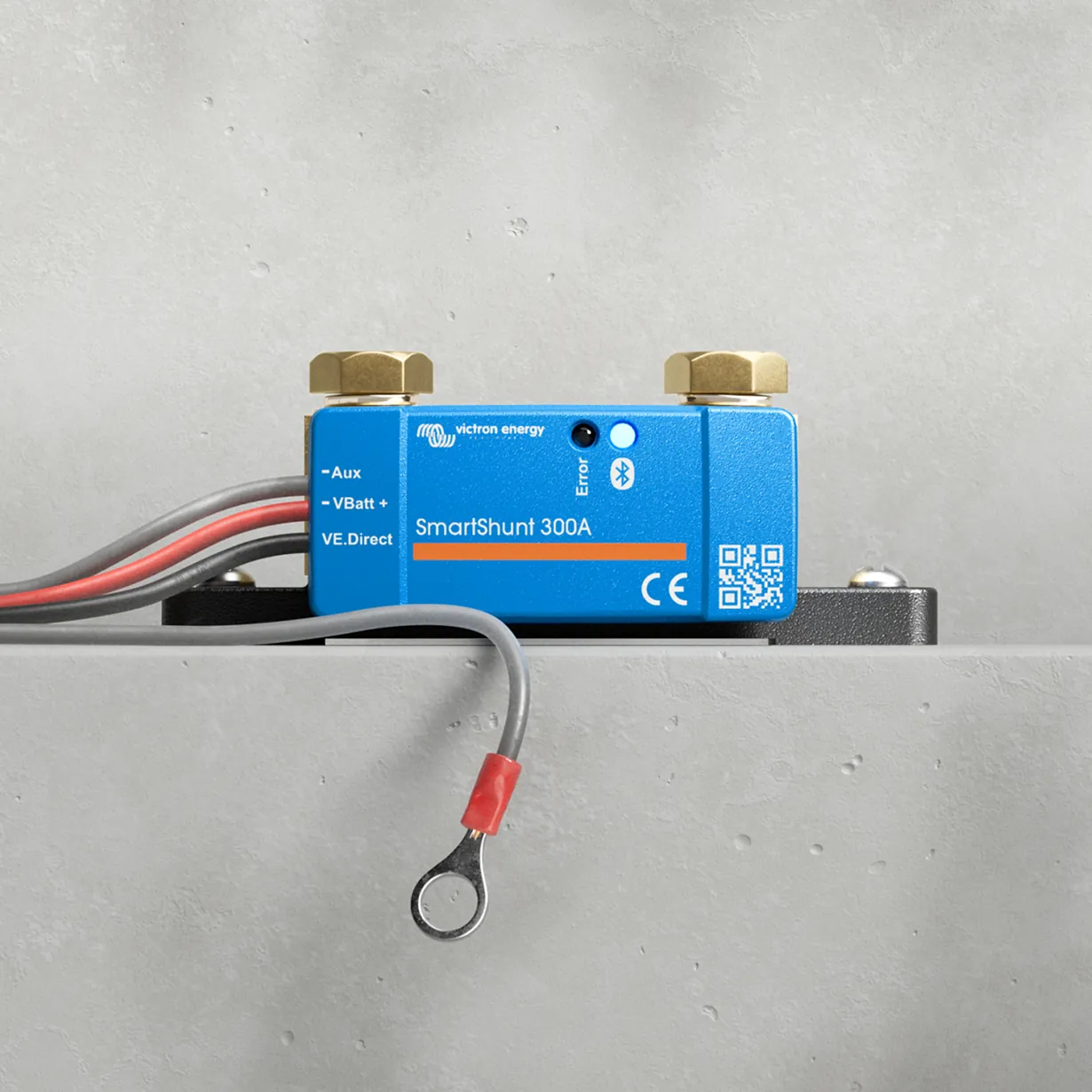
- Every connection adds resistance: about 0.06 mΩ per connection, a 500 A shunt — 0.10 mΩ, a 150 A fuse — 0.35 mΩ (for comparison, 2 m of 35 mm² cable — 1.08 mΩ). Loose, dirty or badly crimped connections are the most common source of problems.
- After installation, measure the voltage drop at full load (for example, an inverter at maximum load): separately on the negative and positive cables, between the device terminal and the battery pole. A thermal camera is also a good test.
05DC fuses
- Every load and every source connected to the battery has its own fuse in the positive cable — regardless of power. Usually there is a main battery fuse, and separate branch fuses downstream.
- Rated current: with one load — matched to the load current or cable capacity, whichever is lower. With several loads in the circuit — to the cable capacity.
- Rated voltage: at least as high as the maximum voltage in the system and intended for DC. Most DC fuses are suitable for 12 and 24 V, but not necessarily for 48 V. DC breakers can be one-way — the connection direction matters.
- Characteristic: in DC circuits with inverters and motors, time-delay is usually used (high starting current).
- Multiple inverters: each with its own fuse of the same type; do not protect them all with one large fuse — a short circuit in one device may not blow it.
- Battery isolator choose for the full DC current; not every isolator can be switched off under load. Removing the main fuse also disconnects the battery for service work.
Lithium batteries: breaking capacity
Lithium batteries can deliver a very high short-circuit current. Fuse breaking capacity is the highest short-circuit current it can safely interrupt — if it is too low, it may burst. In every installation with a lithium battery, at least one fuse in the DC circuit must have a breaking capacity no lower than the maximum expected short-circuit current of the battery bank — Victron treats this as a mandatory safety requirement.
| Fuse | Max. DC voltage | Interrupting capacity |
|---|---|---|
| Class T (Eaton Bussmann) | 160 V | 200 kA |
| Class T (various manufacturers) | 125–300 V | 20 kA |
| NH (various manufacturers) | 250 V | 25 kA |
| ANL (Blue Sea) | 80 V | 6000 A |
| AMX(L) (Eaton Bussmann) | 125 V | 3000 A |
| MEGA (Littelfuse), 70 V | 70 V | 2500 A |
| MRBF (Blue Sea) | 58 V | 2000 A |
| MEGA (Littelfuse), 58 V | 58 V | 1000 A |
Class T combines very high breaking capacity with fast operation and fits the Lynx system; other types can be used if the current, DC voltage and breaking capacity suit the installation. Examples from the official diagrams: Class-T 150 A for each battery in a campervan, Class-T 250/300 A in a Lynx Class-T Power In on a yacht.
Devices in this guide
 Lynx Power In1000 A DC busbars: Power In without fuses (4 connections) and Class-T Power In for two lithium battery strings.
 Lynx DistributorModular 1000 A DC busbars: fused distribution with MEGA fuses and monitoring, battery connection, Class-T fuses.
 Lynx Smart BMS / NGBMS with contactor and current measurement for Smart LiFePO4 or Lithium NG banks.
 LiFePO4 Smart 12,8/25,6 VLithium iron phosphate batteries with Bluetooth — work only with an external BMS.
 MultiPlus-IIInverter/charger with UPS function: pure 230 V sine wave, PowerAssist supports a weak shore connection.
Related
- Wire and fuse calculator — voltage drop for your lengths.
- Earthing and residual current devices.