

Power on a yacht
A 12 V installation on a boat works to different rules: salt and moisture eat away at connections, the hull is the ground instead of an earth, and a cable from the pontoon can dissolve metal under water. Below is a complete system based on Victron’s official drawing BJE-314A — a Lithium NG 400 Ah bank with Lynx Smart BMS NG, four charging sources, 230 V from shore and protection against galvanic corrosion.
Five things you do not have in a land-based installation
The system on a yacht looks similar to that in a campervan, but it works in completely different conditions. These differences determine the choice of materials and what you must not leave out.
- No earth. A boat has no pin in the ground — the common potential is formed by the interconnected metal parts: hull, engine, metal pipes, rail and protective contacts of sockets.
- Galvanic corrosion. When the cable from the pontoon is connected, a hull – water – land – earth – hull circuit is created. Galvanic current eats away at the weakest metal in that circuit.
- Salt and moisture. Cables must have tinned conductors, and connections must be dry and accessible for inspection.
- Movement and heel. The battery bank is mounted low and rigidly, and every cable must be supported so it does not flex in the waves.
- ABYC E-11 rule. The inverter is connected to the bank with four cables and each of them — positive and negative — must independently carry the full load.

400 Ah bank
Two Lithium NG 12.8 V/200 Ah batteries — 5.1 kWh of energy in total, with Class T 250/300 A fuses.
The BMS decides
The Lynx Smart BMS NG, via its ATC and ATD contacts, permits charging and discharging, and communicates with the Cerbo GX over VE.Can.
Four sources
32 A shore power, 4 kW generator, panels on the bimini and an alternator via a DC-DC charger.
Hull protection
The galvanic isolator blocks currents below 1.4 V, while the isolation transformer breaks the circuit completely.
How it is connected
System based on Victron’s official drawing BJE-314A (rev. B): MultiPlus-II 3 kVA, two Lithium NG 200 Ah batteries, Lynx Class-T Power In, Lynx Smart BMS NG, Lynx Distributor, Smart BatteryProtect 220, Cerbo GX, MPPT 100/50 and Orion XS. Hover over or tap a diagram element. The diagram is schematic — check the original drawing for the connection details.
- Four charging sourcesShore and generator via the MultiPlus-II charger, panels via the MPPT 100/50, engine via the Orion XS.
- The BMS decides everythingThe Lynx Smart BMS NG, via its ATC and ATD contacts, permits charging and discharging, and communicates with the Cerbo GX over VE.Can.
- Each circuit protected separatelyClass T 250/300 A on the positive of each battery in the Lynx Class-T Power In; in the Lynx Distributor, MEGA fuses 400 A (MultiPlus-II), 225 A (DC loads via BatteryProtect) and 150 A (MPPT bus, Orion XS and spare); on the busbar itself, 60 A thermal breakers.
- DC loads via BatteryProtectSmart BatteryProtect 220 disconnects them on an ATD signal before the bank discharges too deeply.
- Everything visible in one placeCerbo GX with GX Touch 50 screen controls charging via DVCC and sends data to VRM.
Layout on a yacht
On a boat, placement is determined not by convenience, but by moisture, weight and cable length. Eight points that decide whether the installation survives the seasons.
Slide the diagram sideways to see the whole yacht.
- 1
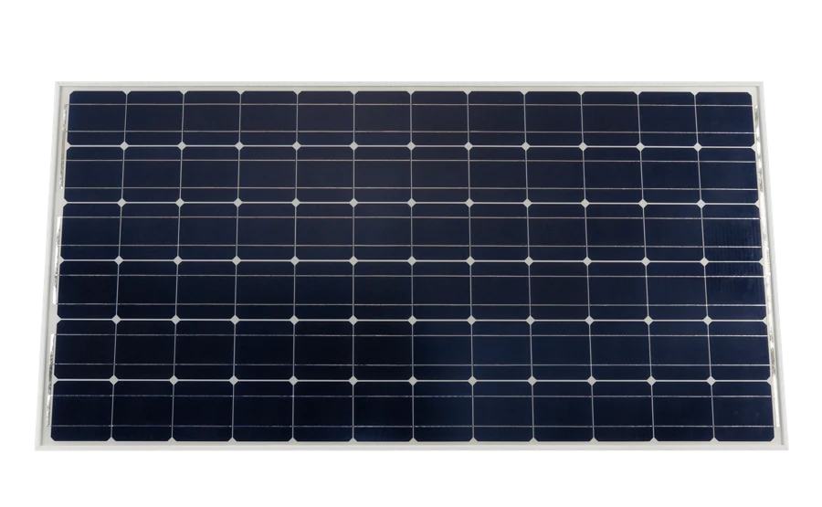 PV panels on the biminiOn a yacht, panels are mounted where the boom and sails do not shade them: on the bimini, on the stern rail, or on the coachroof. The cables are run through a sealed deck gland.
 - 2
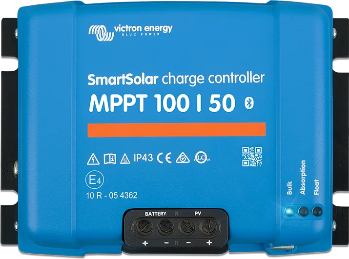 SmartSolar MPPT 100/50The controller is mounted dry and close to the batteries — in a locker or by the distribution panel. In the Victron diagram, its circuit has its own 60 A thermal breaker, and a disconnect on the panel side.
 - 3
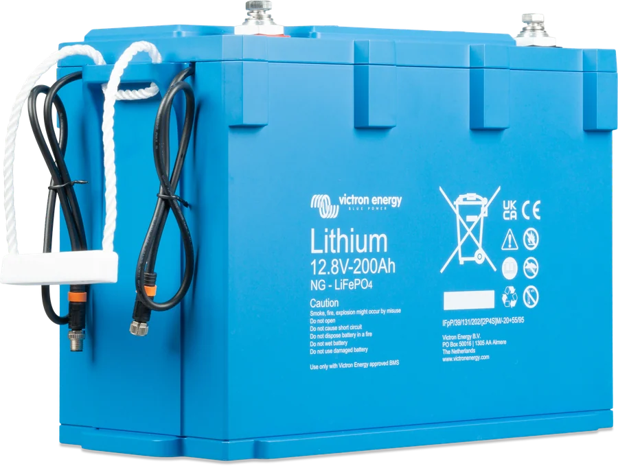 Lithium NG batteriesThe bank under the saloon floor or under a berth — low and close to the vessel’s centreline. NG batteries have Class T 250/300 A fuses in the Lynx Class-T Power In and connect to the BMS with M8 cables.
 - 4
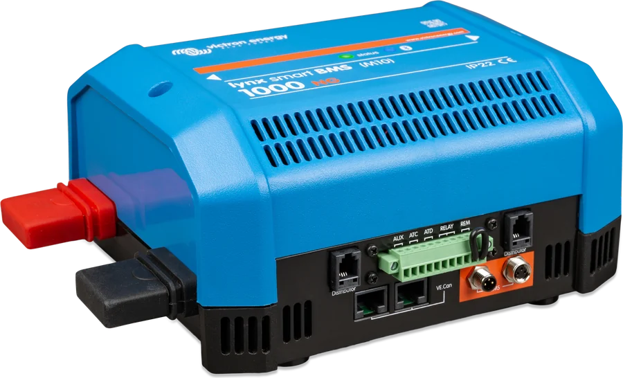 Lynx Smart BMS NGThe heart of the system: it monitors the cells, collects current measurements, and controls chargers and loads. Mount it together with the Lynx Distributor on a common busbar, in a dry and ventilated location.
 - 5
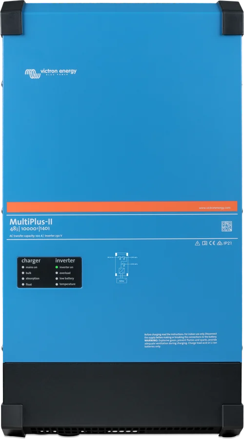 MultiPlus-II 12/3000The inverter/charger as close to the battery bank as possible — on the diagram, four 50 mm² cables (two positives and two negatives) for a distance of up to 5 m. Leave space above and below for airflow, away from the bilge.
 - 6
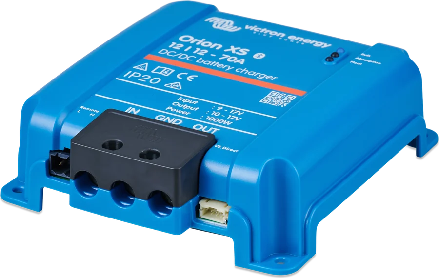 Orion XS and alternatorThe DC-DC charger by the engine. Its input cable is protected by a 60 A thermal breaker, mounted as close as possible to the main starter circuit breaker; the 175 A AMI fuse is the alternator’s factory protection.
 - 7
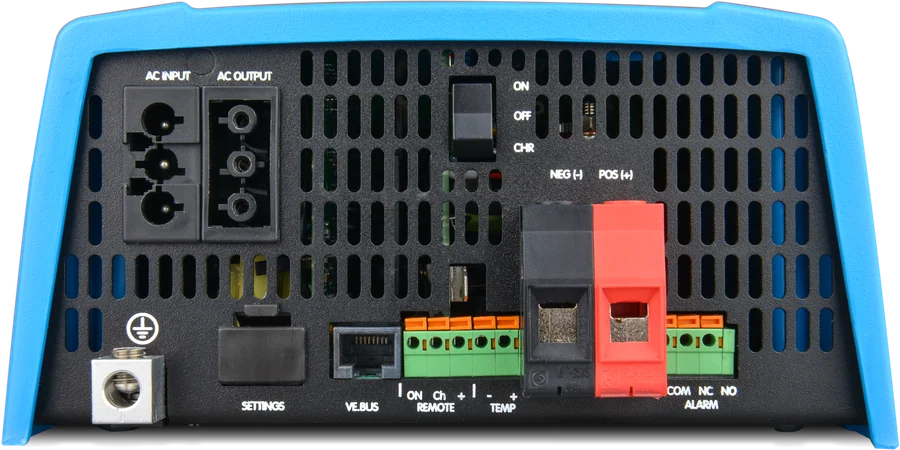 Shore powerShore inlet on the transom or in the cockpit, followed by a breaker, RCD and — if needed — a galvanic isolator or isolation transformer that breaks the corrosion circuit.
 - 8
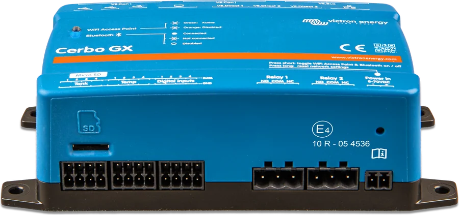 Cerbo GX and displayThe centre at the navigation table: it collects data from the BMS, inverter, MPPT and Orion, controls them via DVCC and sends everything to the VRM portal.
With NG batteries, the BMS controls the installation
In a campervan installation with drop-in batteries, each battery manages itself. Here it is different: the Lynx Smart BMS NG collects data from the cells and only then allows charging and discharging. That is why every source and every load must have its own control path — otherwise the BMS cannot switch them off.
- ATC (allow-to-charge) allows chargers to operate, ATD (allow-to-discharge) — loads.
- DVCC in the GX device digitally controls the MultiPlus, MPPT solar charge controller and Orion XS: the GX tells them the charge current and voltage.
- Pre-alarm warns of an impending shutdown — on the diagram it controls a 12 V / 30 mA buzzer.
| Device | How it is controlled |
|---|---|
| MultiPlus-II (inverter/charger) | digitally via the GX device — DVCC |
| SmartSolar MPPT | digitally via the GX device — DVCC |
| Orion XS | digitally via GX; optionally an ignition wire to the H contact to stop charging when the engine is off |
| DC loads | Smart BatteryProtect 220 controlled by the ATD signal from the BMS |
| AC loads | together with the MultiPlus-II — when the inverter cuts out, they go off |
Set the Smart BatteryProtect to Li-ion “C” mode and 12 V — from the device itself or via Bluetooth. Without this, it cuts out at voltages suitable for lead-acid batteries.
What the BJE-314A diagram shows exactly
| Location | According to the diagram |
|---|---|
| DC cables to the MultiPlus-II 3 kVA 12 V | 0–5 m: 4 × 50 mm²; 5–10 m: 4 × 70 mm² (length measured from the battery to the inverter). In enclosed cable runs, double the cross-section. The values do not include other loads — these must be added when sizing the battery cables, main fuse and breakers. |
| Each DC cable to the inverter | According to ABYC E-11, each of the four cables — two positives and two negatives — must individually carry the full load |
| MultiPlus-II fuse | 400 A |
| Battery fuses | Class T 250/300 A in Lynx Class-T Power In |
| DC loads circuit | 225 A through main breaker 2 to Smart BatteryProtect 220 |
| MPPT busbar, Orion XS and spare | MEGA 150 A fuse in the Lynx Distributor, and on the busbar itself one 60 A thermal breaker per circuit |
| Orion XS input | 60 A thermal breaker as close as possible to main breaker 3 (the 175 A AMI on the diagram is the alternator’s factory fuse, in the engine circuit) |
| AC input | breaker max. 32 A, matched to the source; input current limit set in the MultiPlus |
| AC-out-1 output | with PowerAssist the total current from the inlet and the inverter to 32 + 13 = 45 A; RCD on the output |
| AC-out-2 output | up to 32 A, live only when AC input is present |
| MultiPlus-II chassis earth | to the central negative busbar, with a cable no smaller than the total cross-section of the device’s negative cables (the diagram refers to ABYC rules) |
| Control circuits | Cerbo 1 A, Smart BatteryProtect 0.5 A, pre-alarm buzzer 0.2 A, plus 300 mA when connecting SBP220 GND-/H |
| Starter battery | 12 V / 125 Ah, maintained by a Blue Smart 12 V/5 A charger through a 10 A fuse |
Size the cross-sections of the remaining cables according to the length in your installation — with the calculator or according to the rules in the Cables and fuses section.
Four sources and when each one works
Shore power
Up to 32 A according to the diagram. The MultiPlus-II charger provides up to 120 A, and PowerAssist adds power from the bank when the shore supply is weak.
230 V · 32 APV panels
The 100/50 controller will accept up to 700 W at 12 V. On a yacht, the problem is shade from the sails and boom — that is why the panels go on the bimini or stern rail.
100 V · 50 AAlternator
The Orion XS 12/12-50 charges the bank at up to 50 A (about 700 W continuous power), separating it from the starter battery and protecting the alternator from running at maximum output.
50 A · approx. 700 W4 kW generator
Connected in place of shore power, via a Shore–0–Generator switch. The MultiPlus-II accepts only one AC source at a time.
4 kW
Shore connection, RCDs and earth
A boat connected to the pontoon behaves like an ordinary domestic installation with one difference: it has no local earth electrode and uses the earth brought in by the shore cable. That earth can be poor — marina cables are long and thin — so the boat’s metal parts must be connected to the protective conductor of the shore connection.
When the cable is disconnected, the installation becomes an independent source: current no longer flows to the water, and the vessel’s hull becomes the protective conductor. For the RCD to operate in this mode, the inverter output neutral must be connected to the hull — the MultiPlus-II does this with its internal earth relay.
- AC-out-1 — uninterrupted circuits, powered from shore or from the inverter; distribution board with RCD.
- AC-out-2 — switched circuits, up to 32 A, live only when external AC is present; this is where the water heater or air conditioning goes.
- Starter charger — Blue Smart 12 V/5 A from the AC distribution board maintains the starter battery, which is not charged by the Orion XS.
The AC installation on a boat — shore connection, distribution boards, RCDs, earthing and corrosion protection — should be installed and signed off by an electrician who knows the rules for vessels. The Victron diagram shows a “non-isolated” arrangement, built according to ABYC rules.
Galvanic corrosion — the price of a cable from the pontoon
When you connect a boat to shore power, the protective conductor connects the hull to the shore earth electrode. A closed circuit is created: hull – water – shore – earth electrode – protective conductor – hull. A small galvanic current flows in it, and chemistry is ruthless: the weakest metal in the circuit dissolves.
What fails
The hull, propeller, shaft and other metals under water. The manufacturer states outright that boats have sunk due to galvanic corrosion, and aluminium hulls are particularly vulnerable to it.
Sacrificial anodes
A piece of metal that is less noble than its surroundings and dissolves instead of the hull. Anodes do not stop corrosion — they only delay it, so you need to check them regularly.
What you must not do
Disconnecting the protective conductor from the hull does indeed break the corrosion circuit — but it removes the boat’s earthing and disables the RCD. This is dangerous and not permitted.
| Galvanic isolator | Isolation transformer | |
|---|---|---|
| How it works | Two diodes connected anti-parallel in the protective conductor; they let current through only above the threshold voltage of about 1.4 V | Energy converted to and from a magnetic field — input and output are fully isolated |
| Effectiveness | Blocks galvanic currents with a voltage below the diode threshold | Breaks the corrosion circuit completely, including the path through the neutral conductor |
| RCD | Works — the higher voltage in an earth fault passes through the diodes | Works — on the output it creates its own phase–neutral–protective-conductor arrangement |
| Advantages and disadvantages | Small and light, but it requires a sound protective conductor; corrosion can also flow through the neutral conductor if it is connected to earth somewhere on the boat | Heavier and more expensive, but it isolates the boat from problems in neighbouring installations; it also often lets you change the voltage, for example from 120 V to 230 V |
The Victron drawing provides space for either a galvanic isolator or an isolation transformer at the shore connection — “if needed”, together with the required breakers. The installer decides which solution to use.
What is different from shore-based installations
The rules are the same as in any 12 V installation — voltage drop below 2.5% (that is, 0.3 V), cable cross-section selected for the current and length, each load with its own fuse on the positive cable — but the material must be marine grade.
- Tinned conductors. In damp air and salt, plain copper oxidises and the resistance of connections increases.
- Flexible fine-stranded cables. Rigid, coarse-stranded cables crack from engine vibration and hull movement.
- Class T with lithium batteries. An NG battery bank can deliver a huge short-circuit current — you need a fuse with the right interrupting capacity (Class T is up to 200 kA, a standard 58 V MEGA fuse only 1,000 A).
- Headroom in the table. The currents in the table below were calculated for the total length of the positive and negative cables, with a 0.259 V voltage drop and no losses at the joints.
| Cross-section | up to 5 m total | up to 10 m | up to 15 m | up to 20 m |
|---|---|---|---|---|
| 10 mm² | 30 A | 15 A | 10 A | 8 A |
| 16 mm² | 48 A | 24 A | 16 A | 12 A |
| 25 mm² | 75 A | 38 A | 25 A | 19 A |
| 35 mm² | 105 A | 53 A | 35 A | 26 A |
| 50 mm² | 150 A | 75 A | 50 A | 38 A |
| 70 mm² | 210 A | 105 A | 70 A | 53 A |
| 95 mm² | 285 A | 143 A | 95 A | 71 A |
A quick rule for DC circuits up to 5 m: the cross-section in mm² is the current divided by 3. Instead of one very thick cable, you can use two thinner ones with the same total cross-sectional area.
What to watch out for in this setup
The drawing explicitly requires this from both poles: all positive cables and all negative cables should be as short as possible and the same length. Otherwise the batteries in the bank will work unevenly and one will age faster.
The Lynx Distributor gets address A–D with two DIP switches (factory setting A, as shown in the drawing) — if you have several distributors, each must have a different address; it connects to the BMS with a separate BMS cable. The terminators apply to the VE.Can network between the Lynx Smart BMS NG and the Cerbo GX — they must be fitted at both ends.
The manufacturer recommends reading the manual carefully before installation. The input fuse should be as close as possible to the main switch of the starter circuit.
- Fuses at the end. Fit the main fuse links only after checking all the wiring; at each device, connect the negative first, then the positive.
- Keep clear of the bilge. Mount the inverter, BMS and distribution boards high and dry — water in the bilge will appear sooner or later.
- Common ground. The engine negative, starter battery negative and Orion XS output all return to the central negative busbar.
Boat for winter, installation under control
- Charge the bank fully before putting the boat away and only then switch off the devices — lithium batteries do not like being left for long periods at a low state of charge.
- Keep it connected, if the boat remains in the water: Cerbo GX with a modem shows the bank status and alarms in VRM, including remotely.
- Check the anodes at the end of the season — once worn out, they stop protecting the hull, and in winter at the marina the galvanic current flows just the same.
- Check every few weeks: state of charge, moisture around the equipment and signs of corrosion on the terminals.

Eight mistakes that cost the most
On the water, the most expensive consequences are often those you cannot see: corrosion, moisture and poor fuse selection.
Shore cable without corrosion protection
Without a galvanic isolator or isolation transformer, the hull–water–shore circuit remains closed for the entire stay in the marina. You only see the effect when the boat is lifted out.
Plain copper instead of tinned copper
In salty air, the conductors oxidise from the inside. Resistance rises, voltage drops increase, and connections start to heat up.
MEGA instead of Class T with NG batteries
A lithium bank can deliver a short-circuit current far higher than a standard fuse can interrupt. With Lithium NG, the drawing specifies Class T 250/300 A.
DC loads without BMS control
With NG batteries, everything must be able to be disconnected. The loads are wired through a Smart BatteryProtect controlled by the ATD signal.
BatteryProtect set for lead-acid
After installation, you must set Li-ion “C” mode and 12 V — otherwise the disconnect thresholds will not suit the lithium battery.
Alternator directly to the lithium bank
Without a DC-DC charger, the alternator runs at maximum and charges with a lead-acid profile. Orion XS limits the current and separates the two circuits.
Inverter in the bilge
Moisture and salt end in PCB corrosion. Equipment is mounted high, dry and with enough space for cooling.
No communication during lay-up
Cerbo GX with access to VRM shows the bank status and alarms remotely — for a boat left for several months, this is the cheapest insurance.
Frequently asked questions about yacht installation
How is this system different from a campervan installation?
By the batteries and the control method. In a campervan, drop-in batteries have their own internal BMSs, while here the bank is managed by the Lynx Smart BMS NG: it uses the ATC and ATD contacts to permit charging and discharging, and the GX device controls the chargers via DVCC.
Do I need a galvanic isolator?
If the boat stays in the water and is sometimes connected to shore power — yes, it is worth it. Without one, the protective conductor closes the galvanic circuit between the hull and the shore. A better alternative is an isolation transformer. The Victron drawing provides space for both solutions.
How does a galvanic isolator work?
It is two diodes connected anti-parallel in the protective conductor. They only conduct above a threshold voltage of about 1.4 V — higher than the potential differences between metals, so galvanic current will not flow, while earth fault current will pass and trip the RCD.
Why do I need anodes if I have an isolator?
The isolator only breaks the circuit through the shore connection. Between the metals of the boat itself — the propeller, shaft, hull — small currents still flow. Sacrificial anodes corrode instead of them and need regular inspection.
How much energy does a 400 Ah bank provide?
Two Lithium NG 12.8 V/200 Ah batteries are 2 × 2560 Wh, which is about 5.1 kWh. How much of that you can actually use depends on the thresholds set in the BMS and on how deeply you want to discharge the bank — the manufacturer gives 2,500 cycles at 80% depth of discharge.
Can I connect shore power and the generator at the same time?
No. The MultiPlus-II has one AC input, so sources are switched manually or automatically — on the drawing, the Shore–0–Generator switch is used for this.
Why are there two positive cables to the inverter?
Because at 12 V and 3 kVA the currents are very high. In accordance with ABYC E-11, each of the two cables must be sized so that it can carry the full load on its own.
What about the starter battery?
It is separate — 12 V / 125 Ah. It is maintained by a small Blue Smart 12 V/5 A charger powered from the AC distribution board through a 10 A fuse, and it is isolated from the lithium bank by the Orion XS charger.
Devices in this setup
 Lithium NGVictron’s new generation of LiFePO4 batteries: 12.8/25.6/51.2 V, IP65, built-in current measurement — only with BMS NG.
 Lynx Smart BMS / NGBMS with contactor and current measurement for Smart LiFePO4 or Lithium NG banks.
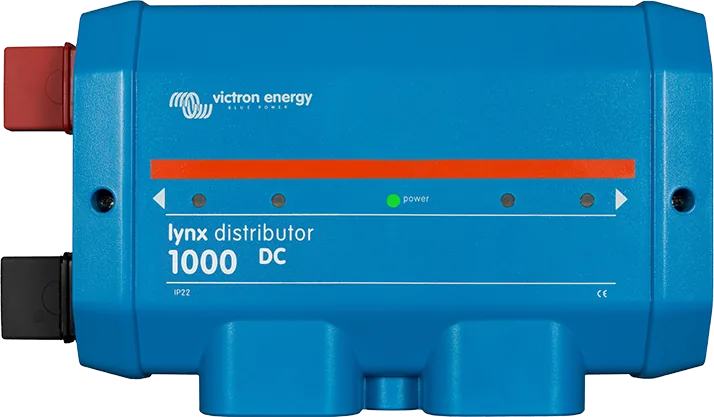
 Lynx DistributorModular 1000 A DC busbars: fused distribution with MEGA fuses and monitoring, battery connection, Class-T fuses.
 MultiPlus-IIInverter/charger with UPS function: pure 230 V sine wave, PowerAssist supports a weak shore connection.
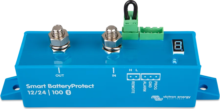
 Smart BatteryProtectDisconnects DC loads before the battery is discharged; in Li-ion mode controlled by the BMS.
 Cerbo GXSystem control centre and gateway to the VRM portal.
 Orion XSDC-DC charger 50/70 A from the alternator, including with a smart alternator.
 SmartSolar MPPT 100/30 and 100/5030 and 50 A controllers for up to 100 V from panels — at 12 V for about 440 and 700 W of panels.
What next
Manufacturer documentation
- Drawing BJE-314A (rev. B) — MultiPlus-II 3 kVA, 2 × 200 Ah Li NG, Lynx Class-T, Smart BMS NG, Distributor, Cerbo GX, SBP 220, generator, MPPT 100/50, Orion XSvictronenergy.com · PDF · EN
- Wiring Unlimited — mobile installations, boat earthing, galvanic corrosion, isolator and isolation transformervictronenergy.com · PDF · EN
Content compared with Victron Energy documentation (datasheets and manuals) — current as of 20 September 2026. Report a content error · Correction log