
01First check
- What exactly was disconnected: charging (chargers, controllers, alternator) or loads. These are two different paths below.
- Code in VictronConnect — in the battery (W-SL, A-SL, E-SL) or in the Lynx Smart BMS (W-B, A-B, E-B). Code meanings: Lithium Smart and Lynx codes.
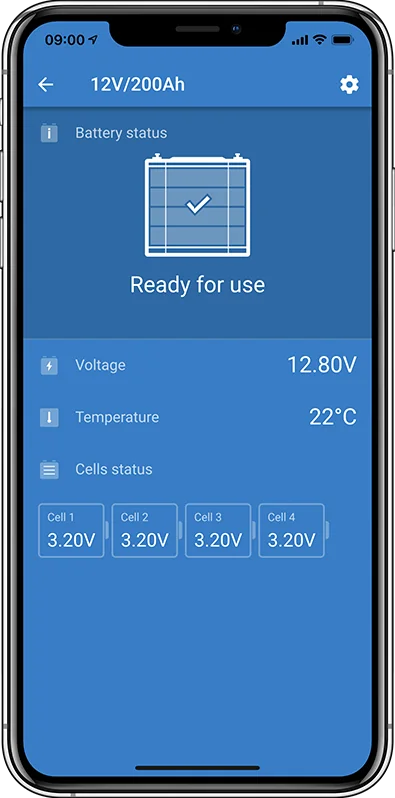
- Cell voltages — VictronConnect shows the voltage of each cell in every battery. This is the most important information for this diagnosis.
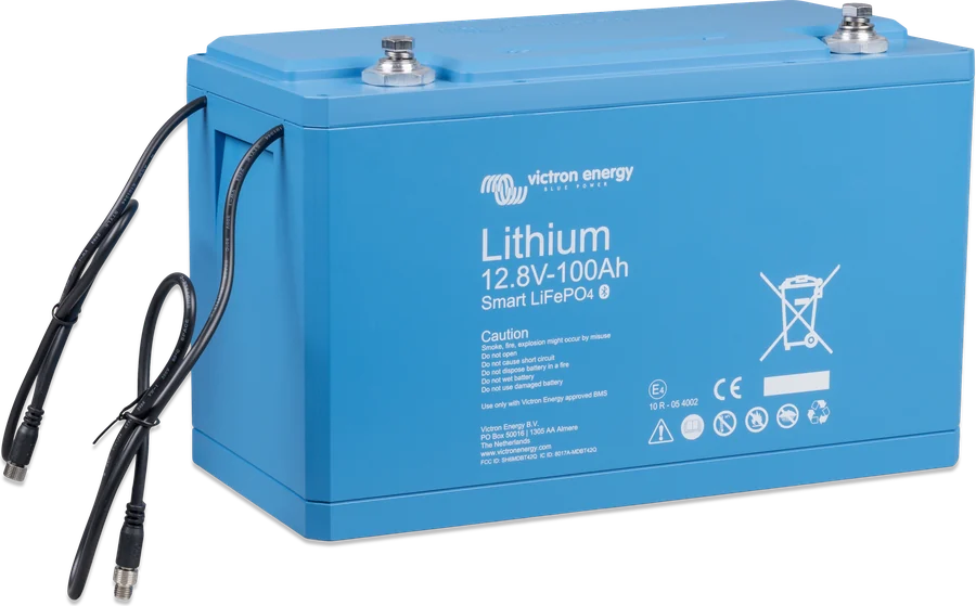
Smart LiFePO4 batteries (12.8 V and 25.6 V) may only be used with an external BMS approved by Victron — the battery itself does not disconnect charging or loads.
02Step-by-step diagnosis
1Is it temperature?
The battery blocks charging when it is too cold (alarm A-SL22) or too hot (A-SL15). Lithium Smart accepts charging from +5 °C to +50 °C.
At low temperature, charging will resume automatically when the battery warms above the threshold. Check in VictronConnect the “Allowed to charge minimum temperature” setting and whether the temperature offset is not set to an unrealistic value — charging below 5 °C voids the warranty. If it is overheating, provide ventilation and clearance around the battery, reduce the charge current or the load.
Go to step 2.
2Is the BMS switching the charger off and on all the time?
This is a sign of cell imbalance. The mechanism is as described in the manual: when one cell reaches 3.75 V, the BMS switches the charger off. The balancer continues moving energy from the highest cell, its voltage drops and below 3.6 V the BMS switches charging on again. This cycle usually lasts 1–3 minutes and repeats until all cells are charged and equalised — with a large imbalance, for up to 12 hours.
This is not a battery or cell fault — the BMS is protecting the cells from overvoltage. Balancing also continues when the charger is switched off.
Let the system finish balancing (step 4). If this keeps recurring regularly, remove the cause (step 3).
Check the cell voltages. If any is above 3.75 V and the others are clearly lower, this is also an imbalance (step 3). If the voltages and temperatures are normal and the alarm persists, go to step 6.
3Where does cell imbalance come from?
The causes listed in the manual:
- Too little time in absorption — for example not enough sun, or the generator runs for too short a time or too infrequently. The manufacturer recommends at least 2 hours of absorption per month in lightly cycled systems (standby, UPS) and 4–8 hours per month in heavily cycled systems (off-grid, ESS).
- The charger never reaches float — it should do so at least once a month; this is also needed to synchronise SoC in the battery monitor.
- Discharged too deeply — a cell may have been permanently damaged.
- Battery nearing end of life or damaged cell — balancing will not fix this.
Watch out for apparent imbalance: if after a day without use one cell drops by 0.1–0.2 V below the others, this is not imbalance, but a damaged cell.
4How do you restore cell balance?
- Charge the battery with a charger set to a lithium profile and controlled by the BMS.
- Balancing works only during absorption. Each time the charger goes to float, you have to restart it manually — this may take several days.
- For a long time it may seem that nothing is happening: cell voltages do not change, and the BMS repeatedly switches the charger off and on. This is normal.
- Balancing continues when the charge current is at least 1.8 A or when the BMS has temporarily switched the charger off. It is nearly finished when the current drops below 1.5 A and the cells are at about 3.55 V; it finishes when the current drops further and all cells are at 3.55 V.
How long it takes: the balancing current is 1.8 A per battery (in the 12.8 V/50 Ah model — 1 A). Example from the manual: in a 200 Ah battery, one cell charged to 50% needs 100 Ah, so at least 100 / 1.8 ≈ 55 hours of absorption — with a 2-hour absorption period, that is about 27 manual charger restarts.
For installers, the manufacturer suggests how to avoid restarts. During balancing, the charger should maintain the absorption voltage appropriate for the system: 14.2 V for a 12.8 V battery, 28.4 V for a 24 V system or 56.8 V for a 48 V system (for example float and storage set to that voltage, or a very long absorption time). After balancing, you must return to the normal lithium profile. Never leave such settings in an operating system — such a high voltage shortens battery life.
The manufacturer stresses: you must be 100% sure that the BMS controls the charger — otherwise there is a risk of dangerous cell overvoltage. Check this in VictronConnect: the voltage of the charged cells slowly rises to about 3.7 V, the BMS then switches the charger off and the voltages drop. The cycle repeats until balance returns.
5Has the BMS cut off the loads too early?
The BMS switches the loads off when any cell drops below the “Allowed to Discharge” threshold set in the battery (range 2.6–2.8 V, default 2.8 V). The most common cause of premature cut-off is cell imbalance (steps 3–4) — one weaker cell reaches the threshold even though the battery’s total voltage looks fine.
- Check the cell voltages of all batteries connected to the BMS.
- Check whether all batteries have the same “Allowed to Discharge” setting.
- After cut-off due to low cell voltage, the BMS will switch the loads back on only when all cells reach at least 3.2 V — that is, after the battery has been charged.
If the battery is very deeply discharged (below 10 V for 12.8 V) — see deeply discharged lithium battery.
6Alarm, even though voltages and temperatures are normal?
First make sure that the cell voltages and temperatures of all batteries are within range. Remember that after a low-voltage alarm all cells must reach 3.2 V before the battery clears the alarm. Possible cause: a loose or damaged BMS cable or connector — check them all.
Test: BMS or battery? (procedures from the manual)
- One battery: disconnect both BMS cables from the BMS and connect its two connectors with one BMS extension cable (in a loop) — the BMS then “sees” the battery without an alarm. If the alarm continues, the BMS is faulty. If it disappears, the battery is faulty.
- Several batteries: disconnect both BMS cables of one battery and connect the cables of neighbouring batteries to each other (or of the battery and BMS), bypassing it. If the alarm disappears, the bypassed battery is at fault; if not, repeat for the next one. If the alarm continues after bypassing all batteries, the BMS is faulty.
Is the BMS working at all? Disconnect one battery BMS cable — a working BMS should go into alarm state.
7Cell overvoltage alarm (A-SL9)?
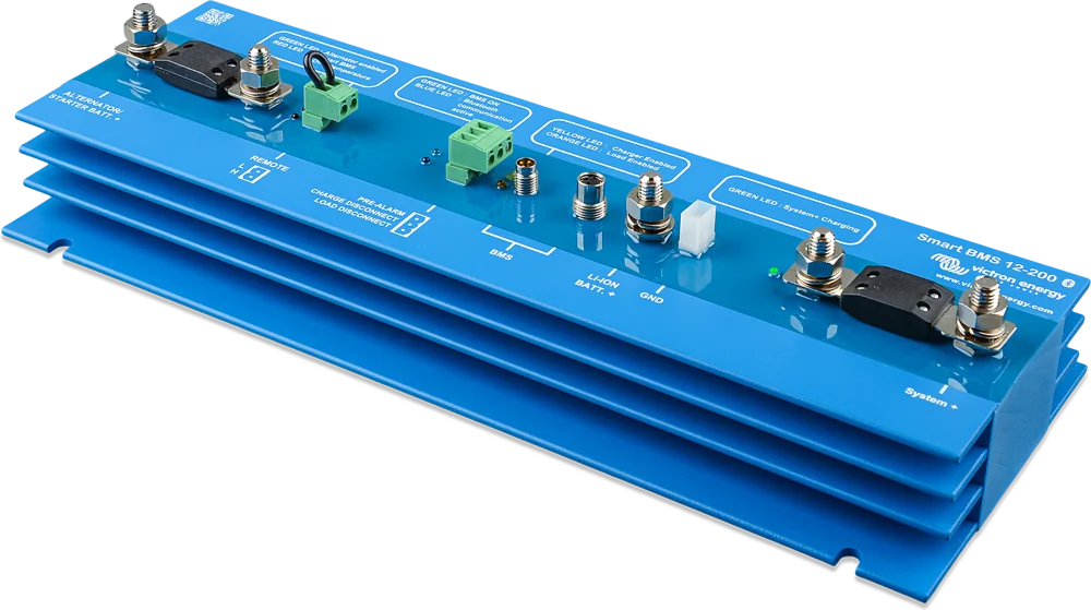
This means that one charger is not being disconnected by the BMS. Switch off all chargers immediately. Ask the installer to check whether each of them (including the alternator via the DC-DC charger and the solar charge controllers) is controlled by the BMS charge disconnect contact (in the Lynx Smart BMS: ATC). With correct control, the BMS disconnects the chargers before it raises this alarm.
03Lynx Smart BMS: additional causes
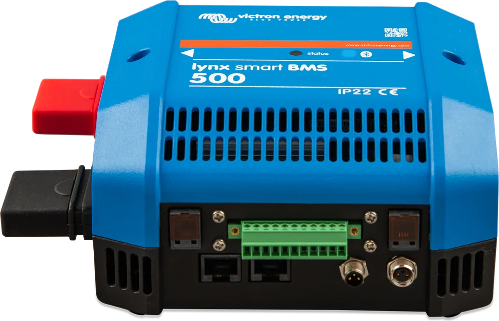
- High current (A-B02) — reduce the charge current or switch off part of the loads; the system will try to switch them back on automatically after 5 minutes.
- Low SoC (A-B07) — charge the battery; the loads will return automatically.
- ATC/ATD fault (E-B36) — make sure all chargers and loads are controlled by DVCC or by the ATC/ATD contacts.
- Red Status LED flashes 3 times every 4 seconds — cell voltage too high or too low, or temperature (full flash table).
04Lithium NG with VE.Bus BMS NG or smallBMS NG
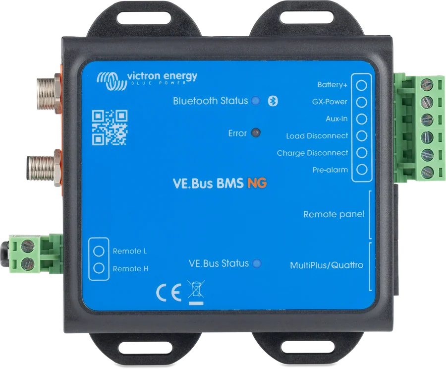
The Lithium NG battery manual describes cell imbalance, balancing (charger turned off at 3.75 V, turned on below 3.6 V, balancing current 1.8 A) and BMS tests in the same way as steps 2–4 and 6 above. Differences:
- Load disconnect threshold — the BMS disconnects loads when a cell drops below the battery’s fixed minimum of 2.6 V (in Lithium Smart the threshold is adjustable, default 2.8 V). Loads return when all cells reach at least 3.2 V.
- “Allowed to charge: No” in VictronConnect — causes according to the BMS manual: battery temperature below 5 °C (A-B13), temperature too high (A-B09), a cell has reached the upper voltage threshold (stored permanently in the battery), and on VE.Bus BMS NG also remote shutdown.
- “Allowed to discharge: No” — the set Discharge floor has been reached (factory default 10%; A-B07), a cell has reached the fixed lower voltage threshold, and on VE.Bus BMS NG also remote shutdown. With a pre-alarm, the field shows “Pre-Alarm”.
How VE.Bus BMS NG stops charging. With high cell voltage or low temperature, charging must stop:
- System with GX device — DVCC must be enabled. The GX then sets the charge current limit to zero for solar chargers, Inverter RS, Multi RS and inverter/chargers. The BMS does not control charge voltage: in ESS the charging algorithm is set in the Multi, and in an off-grid system each device must have the correct lithium profile.
- Without GX or with a charger not compatible with DVCC — the BMS Charge disconnect output (normally high, equal to battery voltage) is connected to the H terminal of the charger remote connector. With high cell voltage or low temperature, the output goes floating and the charger switches off. For chargers with reverse logic, use the “Inverting remote on-off cable” or a Cyrix-Li-Charge relay. The alternator is controlled through a DC-DC charger (e.g. Orion-Tr Smart) or a SolidSwitch 104 — also via the Charge disconnect output.
Inverter/charger with VE.Bus BMS NG (questions and answers from the BMS manual):
- A low cell voltage signal switches the inverter/charger to “charger only” mode — it charges when AC is available, and without AC it is off.
- A high cell voltage signal appears only with unbalanced cells — the inverter/charger goes to bulk with reduced current so the balancer can equalise the cells.
- If the inverter/charger cannot find the BMS (for example, the BMS is disconnected), it goes to emergency mode: it charges at up to 5 A to 12, 24 or 48 V and only the “Mains on” LED is lit. Without AC, it switches off and will not start operating as an inverter.
- The batteries are empty and the inverter/charger is not charging — connect a small charger (for example, 5 A) and wait until the battery voltage returns to 12, 24 or 48 V. To start a Quattro with empty or disconnected batteries, you must supply it from AC input 1 — powering AC input 2 will not start it.
- The BMS reports VE.Bus Error 15 — the inverter/charger firmware is older than xxxx415; update it if a newer version is available.
- The VE.Bus BMS NG remote connector must have at least a bridge between L and H — otherwise the BMS will not switch on. Remote shutdown leaves the inverter/charger in low-power mode (without charging or discharging), even when AC is connected.
05Lithium SuperPack NG (BMS in the battery)
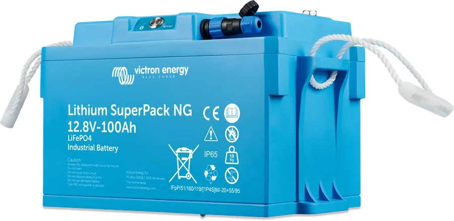
When ATC (allow to charge) or ATD (allow to discharge) is off, VictronConnect shows the reason — tap the “i” icon next to the “No” status. Description of all reasons: ATC/ATD shutdown reasons. Most SuperPack NG protections restore operation automatically:
- Short circuit — the battery tries up to three times (every 30 seconds) to turn the output back on. If the short circuit persists, it reports E-B25 and blocks charging and discharging; once the short circuit is removed, it switches them back on by itself. If the output voltage rises but normal operation does not return, discharging stays off (charging allowed), and the attempts repeat every 10 minutes.
- Overcurrent — charging or discharging switches off within 5 seconds of exceeding the maximum continuous current (faster above 3C) and returns no later than after 5 minutes. There is no permanent lockout — the cycle repeats until the cause disappears.
- Low voltage — warning W-B01; if it does not clear within 30 seconds, ATD switches off and alarm A-B01 appears. It clears when the battery returns to the operating range.
- Temperature — protection against too high and too low temperature resets automatically when the battery temperature returns to the range.
- Safety lockout (E-B44) — when a cell, for example due to self-discharge, drops below the lockout threshold, discharging switches off, and after 30 seconds charging also switches off. This lockout does not reset automatically: after the cause has been removed, a full battery power-off and power-on is required. Deep discharge can permanently damage the cells — see the procedure after very deep discharge.
06When it is a fault or end of battery life
According to the manual, the signs of a fault are: a cell that, after the battery is taken out of service, drops clearly below the others, a loop test indicating the battery or BMS (step 6), and E-SL error codes. Loss of capacity may also be due to battery age (number and depth of cycles — check the history in the battery monitor or Lynx Smart BMS). Deep discharge, end of service life, charging below 5 °C, mechanical damage, moisture ingress and operation without a Victron-approved BMS are not covered by warranty. For repair or replacement, contact the dealer or installer; have the serial number, firmware version, cell voltage screenshots and history from the battery monitor ready.
Devices this applies to
 LiFePO4 Smart 12,8/25,6 VLithium iron phosphate batteries with Bluetooth — work only with an external BMS.
 Lynx Smart BMS / NGBMS with contactor and current measurement for Smart LiFePO4 or Lithium NG banks.
 smallBMS NGSimple BMS for Lithium NG batteries without VE.Bus — controls chargers and loads via outputs, with Bluetooth.
 VE.Bus BMS V2BMS for Lithium Smart batteries in a system with MultiPlus or Quattro — controls the inverter, chargers and loads.
 Lithium NGVictron’s new generation of LiFePO4 batteries: 12.8/25.6/51.2 V, IP65, built-in current measurement — only with BMS NG.
 VE.Bus BMS NGBMS for Lithium NG batteries in a system with MultiPlus or Quattro — Bluetooth, SoC on GX, discharge floor.
 Lithium SuperPack NGDrop-in LiFePO4 battery with built-in BMS, heater and IP65 — a simple replacement for a lead-acid battery in a campervan.
Sources
- Lithium Smart Battery Manual (rev 21), chapter 6 “Troubleshooting & support”victronenergy.com · PDF · EN
- Lynx Smart BMS — manual, appendix “Warning, alarm and error codes”victronenergy.com · EN
- Lithium NG Battery Manual 12.8 V — chapter 6: troubleshooting (HTML version, as of 21 September 2026)victronenergy.com · EN
- VE.Bus BMS NG — chapter 3: controlling chargers, DVCC, Charge disconnect, remote on/offvictronenergy.com · EN
- VE.Bus BMS NG — chapter 5: Allowed to charge / discharge, codesvictronenergy.com · EN
- VE.Bus BMS NG — chapter 6: questions and answers (inverter/charger, emergency mode, VE.Bus Error 15)victronenergy.com · EN
- smallBMS NG — chapter 5: Allowed to charge / dischargevictronenergy.com · EN
- Lithium SuperPack NG — chapter 6: automatic protections, ATC/ATD causes (HTML version, as of 21 September 2026)victronenergy.com · EN