
01What DVCC does
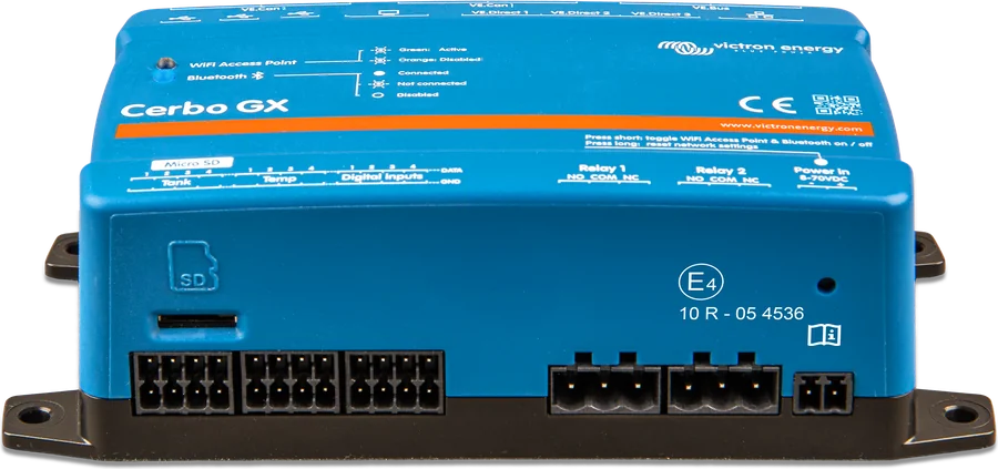
DVCC (Distributed Voltage and Current Control) is enabled on the GX device in Settings → System Setup → Charge Control. According to the manual, this changes the GX “from a passive monitor into an active system controller”. Which functions work depends on the battery type, the Victron devices installed and their configuration:
- Battery with BMS on CAN-bus (including Lynx Smart BMS and Lynx Smart BMS NG) — the GX receives limits from it and passes them to inverter/chargers, solar charge controllers and Orion XS chargers. These switch off their own charging algorithm and do what the battery tells them.
- Lead-acid battery — DVCC provides a shared charging current limit for the whole system, plus temperature sharing (STS) and current sharing (SCS).
02What the battery sends: CVL, CCL and DCL
A smart BMS connected via CAN-bus sends three values to the GX:
| Abbreviation | Meaning |
|---|---|
| CVL | Charge Voltage Limit — the highest charging voltage the battery will accept right now |
| CCL | Charge Current Limit — the maximum charging current requested by the battery |
| DCL | Discharge Current Limit — the maximum discharge current the battery allows |
Some batteries send variable values — calculated live from cell voltages, state of charge or temperature — while others send fixed values. With such batteries, you do not need to connect the ATC and ATD wires to the MultiPlus or Quattro AUX inputs.
- Charging settings in the devices stop mattering. The voltages and charge profiles set in VEConfigure or VictronConnect “have no effect” — MultiPlus, Quattro, Multi RS and Inverter RS, MPPT controllers and Orion XS charge with the voltage sent by the battery. This also applies to systems with Lynx Smart BMS and Lynx Smart BMS NG.
- “Ext. control” state. Controlled devices show “Ext. control”; MPPT and Orion XS LEDs then show bulk and absorption, never float.
- DCL = 0 during off-grid operation. MultiPlus and Quattro switch off the inverter when the battery sets zero discharge current, and switch back on automatically when grid power returns or when the BMS raises DCL.
03Who controls whom
- Battery with BMSSends CVL, CCL and DCL limits to the GX; with Lynx Smart BMS, DVCC is always enabled.
- Battery monitorThe GX distributes its voltage (SVS), temperature (STS) and current (SCS).
- GX deviceSettings → System Setup → Charge Control; firmware from v2.12.
- Controlled devicesMultiPlus and Quattro via VE.Bus, MPPT controllers via VE.Direct or VE.Can, Orion XS via VE.Direct.
- No communicationOrion-Tr Smart, Skylla-i, alternator — only by ATC/ATD wires from the BMS.
What is controlled and what is not
| Device | Controlled by DVCC? | Condition |
|---|---|---|
| MultiPlus / Quattro on the GX VE.Bus port | yes | firmware from 422 (MultiGrid from 424); also applies to parallel and three-phase systems |
| Second MultiPlus / Quattro via MK3-USB | only after enabling the option | “Managed battery controls all Multis and Quattros” — each unit gets the full CCL, so the installer must keep the total current in check |
| VE.Direct MPPT controllers | yes | firmware from v1.46 |
| VE.Can MPPT controllers with VE.Direct port | yes | firmware from v1.04 |
| Older VE.Can regulators with display | no | according to the manual, you cannot use them with DVCC |
| Multi RS, Inverter RS, MPPT RS | yes | firmware from v1.08 |
| Orion XS | yes | firmware from v1.00 |
| Skylla-i, alternator and other chargers without a GX connection | no | their current is not counted in the limit; control only via ATC/ATD wires |
| Orion-Tr Smart | no | there is no VE.Direct port; it is switched off with the remote wire from the ATC / Charge Disconnect BMS output |
If a device’s firmware is too old, from Venus OS v2.40 the GX shows error #48 — DVCC with incompatible firmware. The manual recommends: when commissioning, install the latest software, and when troubleshooting, start with updates.
04When to enable DVCC — depending on the battery
The manual states that DVCC is fully supported for lead-acid batteries (gel, AGM, OPzS), for Lithium Smart with VE.Bus BMS and Lynx Ion (+ Shunt) BMS, and for Lithium NG with VE.Bus BMS NG. With Lynx Smart BMS and Lynx Smart BMS NG, DVCC is enabled automatically and cannot be turned off. Third-party CAN-bus batteries — only if the Victron compatibility page explicitly lists DVCC as supported; if there is no mention of DVCC, do not enable it.
| Setting | Lead-acid | VE.Bus BMS V1 | VE.Bus BMS V2 and NG |
|---|---|---|---|
| Shared charge current limit | yes | yes | yes |
| SVS | yes | ESS: disabled; other systems: enabled when there is a BMV or SmartShunt, otherwise disabled | like V1 |
| STS | yes | no | no |
| SCS | yes | like SVS | like SVS |
| ATC and ATD wires | — | yes | not for regulators, inverter/chargers, Multi/Inverter RS and Orion XS; other loads and chargers — by wires |
With VE.Bus BMS V2 and VE.Bus BMS NG, DVCC must be enabled for the GX to control solar chargers, Inverter RS and Multi RS. With third-party batteries, some settings come from the BMS and some must be set manually — depending on the model on the Victron battery compatibility list. Example of such a system: workshop bus with VE.Bus BMS V2.
05Charge current limit
“Limit charge current” in the Charge Control menu sets the maximum total charging current in the system. The GX distributes it in this order: first MPPT solar chargers (including MPPT RS), then Orion XS, and finally inverter/chargers (including Inverter RS and Multi RS).
- The lower value wins. When a CAN-bus BMS asks for a different current than the one set in the GX, the lower of the two applies. The limit set in the device itself also still applies — the manual’s example: 50 A in VEConfigure and 100 A in GX gives 50 A.
- AC loads are taken into account. When the inverter draws 10 A for AC loads and the limit is 50 A, the chargers may charge at up to 60 A.
- DC loads — only with a “DC system” monitor. Without it, with a 50 A limit and 20 A of DC loads, the battery gets 30 A. When a SmartShunt configured as a “DC system” meter shows 25 A, the chargers get 50 + 25 = 75 A.
- Other sources are outside the limit. Chargers without a GX connection and the alternator provide extra current, invisible to DVCC — even if a battery monitor is installed.
Example from this site: in the workshop bus, two Orion-Tr Smart (60 A) units are not controlled, so the DVCC limit must allow for their current.
06SVS, STS and SCS — shared measurements
| Function | What it does | Notes |
|---|---|---|
| SVS — Shared Voltage Sense | broadcasts one battery voltage to VE.Bus devices, VE.Direct and VE.Can regulators, Orion XS, Inverter RS and Multi RS; first from the BMS or BMV, as a last resort from VE.Bus | enabled by default with DVCC; forced on with Lynx Smart BMS and BMS NG, forced off with some batteries |
| STS — Shared Temperature Sense | broadcasts battery temperature to inverter/chargers, regulators and Orion XS; source: BMV-702/712, SmartShunt, Lynx Shunt VE.Can, GX input, MultiPlus/Quattro or a regulator with sensor | forced off with Lynx Smart BMS, Lynx Smart BMS NG and some batteries with BMS |
| SCS — Shared Current Sense | broadcasts battery current from the monitor to regulators and Orion XS — until absorption ends by tail current | only without ESS and without batteries with BMS; regulator from firmware v1.47 |
“Controlling BMS” lets you choose the BMS that controls DVCC when there are several in the system — and at the same time calculate SoC with a SmartShunt or BMV. “Limit managed battery charge voltage” is only for temporarily reducing voltage in the first weeks of operation of some batteries (the manual mentions BYD and Pylontech); using it for anything else may block cell balancing.
07DVCC in an ESS system
- The “Keep batteries charged” mode works correctly only with DVCC enabled, and the ESS assistant must be version 164 or later.
- In Optimized mode, when SoC falls by 5% or more below “Minimum SoC”, the system will automatically top up the battery from the grid to that value.
- In Optimized mode with “Feed-in excess solar charger power” enabled, and in “Keep batteries charged” mode, the chargers get a constant 0.4 V addition to the voltage (value for 48 V; for 12 V — four times less).
- Feeding excess power from MPPT disables the current limit. With “Feed-in excess solar charger power”, DVCC does not limit current from the chargers to the battery — otherwise export would not be possible. Battery voltage limits and limits set in the chargers themselves still apply.
- After disconnecting the BMS in an ESS system, the chargers stop with error #67 — No BMS.
ESS modes and settings in practice: home with energy storage. When ESS takes power from the grid instead of the battery: troubleshooting.
08Most common pitfalls
- DVCC with a battery not on the compatibility list. The manual says plainly: if the compatibility page does not mention DVCC, do not enable it.
- Voltages entered in the devices. With a battery with BMS, they are ignored — charging ends according to CVL, not according to the profile in VictronConnect.
- Chargers outside GX. The alternator, Skylla-i or Orion-Tr Smart charge “above the limit”; without ATC/ATD wires the BMS will not stop them.
- A second inverter via MK3-USB. Without the “Managed battery controls all Multis and Quattros” option, it works according to its own settings, and with it each unit gets the full CCL.
- Firmware too old. Error #48; older VE.Can regulators with display do not work with DVCC at all.
When the BMS has blocked charging or discharging: “BMS has cut off charging”.
09How to set up DVCC in GX
- Update the software of all devices — at least to the version in the table above.
- Check the battery against the Victron compatibility list (for third-party batteries) and whether DVCC is supported for it.
- Enable DVCC in Settings → System Setup → Charge Control (it is already enabled with Lynx Smart BMS).
- Set the charge current limit according to the battery manufacturer’s recommendation, allowing for sources that the GX does not control.
- Set SVS, STS and SCS according to the table for your battery and choose “Controlling BMS” if there is more than one BMS.
- Check operation — controlled devices should show “Ext. control” (with a battery with BMS or in ESS).
Discrepancies in the sources: in section 12.4.1 the manual says the limit applies to “inverters/chargers and MPPT charge controllers, nothing else”, yet a few sentences earlier it also lists Orion XS in order — we assume Orion XS is controlled, in line with the firmware table and the Lynx Smart BMS NG datasheet. In the firmware table the BMS is called “Lynx BMS NG”, elsewhere in the chapter “Lynx Smart BMS NG”. The ESS manual states briefly that “Feed-in excess solar charger power” disables the DVCC current limit; the GX manual adds that voltage limits and limits in the controllers themselves continue to work.
Devices in this guide
 Cerbo GXSystem control centre and gateway to the VRM portal.
 Ekrano GXGX centre with built-in 7″ touchscreen.
 MultiPlus-IIInverter/charger with UPS function: pure 230 V sine wave, PowerAssist supports a weak shore connection.
 SmartSolar MPPT 75/10–100/20Small solar controllers with Bluetooth for campervans, boats and cabins.
 Orion XSDC-DC charger 50/70 A from the alternator, including with a smart alternator.
 Lynx Smart BMS / NGBMS with contactor and current measurement for Smart LiFePO4 or Lithium NG banks.
 VE.Bus BMS NGBMS for Lithium NG batteries in a system with MultiPlus or Quattro — Bluetooth, SoC on GX, discharge floor.
 VE.Bus BMS V2BMS for Lithium Smart batteries in a system with MultiPlus or Quattro — controls the inverter, chargers and loads.
 SmartShuntBattery monitor with 300–2000 A shunt, read on your phone or on a GX device.
 Multi RS SolarInverter/charger 48 V, 6 kVA, with two 450 V MPPT trackers — a hybrid for an off-grid cabin and 48 V systems.
Sources
- Cerbo GX manual, ch. 12 “DVCC” — 12.1 functions and recommended settings, 12.2 requirements and firmware, 12.3 charge algorithm, 12.4 current limit, SVS, STS, SCS, 12.5 CAN-bus batteries, 12.6 ESS (as of 22 September 2026)victronenergy.com · EN
- ESS design and installation manual, sec. 4.3.5 “Feed-in excess solar charger power”victronenergy.com · EN
- Lynx Smart BMS NG — datasheet: controlling inverters, Orion XS and charge controllers via GX and DVCCvictronenergy.com · PDF · EN
- VE.Bus BMS V2 — datasheet: disabling VE.Direct and VE.Can charge controllers via a GX devicevictronenergy.com · PDF · EN