
01First check
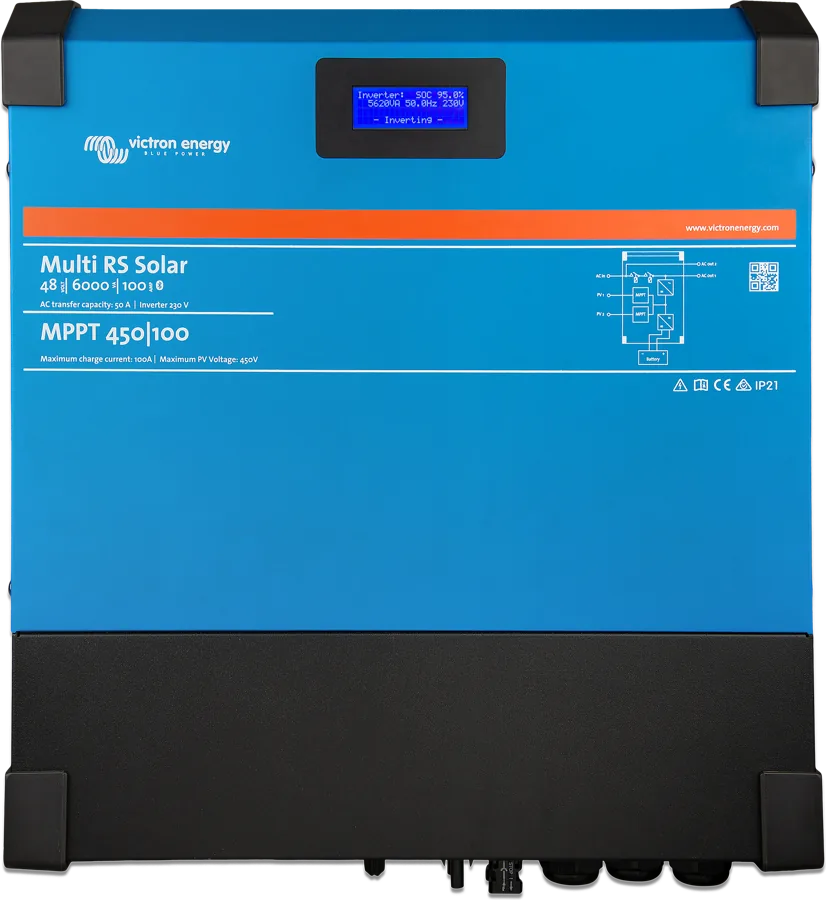
- Display — shows inverter status (power, frequency, AC voltage), battery status (power, current, voltage, state of charge), and on Multi RS Solar also the AC input status and data from each MPPT tracker. A flashing warning icon means an error or warning — you can read its number in VictronConnect.
- Battery data on the display (according to the Multi RS Solar manual) refers to what the device measures at its own terminals — it does not take account of other charging sources or loads in the system (temperature and state of charge may come from the battery monitor).
- GX device (for example, Cerbo GX) connects only via VE.Can. The VE.Direct port is for a computer and for GlobalLink 520. RS devices do not support the VE.Smart network.
| Code | Meaning | Step |
|---|---|---|
| 50, 52 | inverter overload, peak current | 2 |
| 57 | AC voltage at the output before the inverter switches on | 2 |
| 53, 54 | the inverter does not maintain output voltage (low battery, high load) | 3 |
| 2, 51, 17 | battery voltage too high, overheating | 4 |
| 41, 42, 43 | panel insulation, leakage current, earth fault | 5 |
| 29, 33 | overcharge protection, PV overvoltage | 6 |
| 67 | lost connection with BMS | 7 |
| 65, 66, 69–77 | communication, network configuration and three-phase configuration | 8 |
Full descriptions of all codes: charger, MPPT and RS device error codes.
There is very high voltage on the PV cables (up to 450 V DC), even when the panel array is disconnected — the manual reserves PV-side measurements for a trained electrician. Connecting the battery with reverse polarity destroys the device and is not covered by the warranty — check polarity with a multimeter before connecting. PV overvoltage damages the controller (also without warranty).
02Step-by-step diagnosis
1Does the device not switch on?
- The main switch must be in the on position — the remote connection only works then.
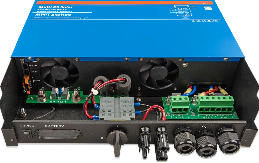
- Remote connection (REMOTE_H and REMOTE_L) — factory bridged. In “Remote on/off” mode, the device switches on when the contacts are bridged or closed by a switch, when H is connected to battery positive, or when L is connected to negative. It switches off when the bridge is removed and the contacts are open.
- “2-wire BMS” mode (battery settings → Remote mode) — two BMS contacts control discharge (REMOTE_H) and charging (REMOTE_L) separately. When both contacts are open, the device switches off. In Multi RS Solar, bridged H and L without a connection to +48 V mean that the device is operating, but charging is blocked — after changing mode, the bridge must be replaced with wires from the BMS.
- Battery voltage — operating range 38–62 V, minimum start voltage 41 V, disconnect at overvoltage 65.5 V.
In Multi RS Solar in a system with several devices (for example, three-phase), it is enough to connect the remote wires to one of them — the contact state is passed to the others via VE.Can.
Go to step 2.
Check the switch, bridge or connection with the BMS, and the battery voltage at the device terminals.
2Does the inverter shut down under load (50, 52)?
Motors and pumps draw a high current at start-up, which can exceed the overcurrent threshold. The inverter then quickly lowers the output voltage to limit the current. If the threshold is exceeded continuously, the inverter switches off for 30 seconds and then switches itself back on. After three restarts, if an overload occurs again within 30 seconds, it switches off. To resume operation: disconnect the loads, switch the device off and on again.
- Continuous power at 25 °C rises linearly from 4600 W at 46 V to 5200 W at 52 V; at 40 °C it is 4500 W, at 65 °C — 3000 W.
- Peak power (with a cold device): 9 kW for 3 seconds, 7 kW for 4 minutes. In Multi RS Solar, after about 4 minutes an additional 25 A AC output current limit applies.
- Error 57 — there is already AC voltage on the output before the inverter is switched on. Check whether the output is connected to a mains socket or another inverter. The error does not clear by itself — after correcting the installation, restart the unit with the switch.
3Shuts down at low battery voltage (53, 54)?
The inverter shuts down when the voltage drops below the shutdown threshold (factory setting 37.2 V), and restarts after at least 30 seconds if the voltage rises above the restart threshold (factory setting 43.6 V). After three such cycles, if it shuts down again due to low voltage within 30 seconds of restart, it stops trying. Then switch the unit off and on and reduce the loads so the panels can top up the battery — or charge it with another MPPT or battery charger. You can change the thresholds in VictronConnect; Dynamic cut-off can be used instead.
- Error 53 and Error 54 — at low battery voltage and high load, the inverter cannot maintain the correct output voltage. Charge the battery or reduce the AC load. The Multi RS Solar manual adds: if Error 54 appears immediately after switch-on, with no load and a full battery, the most likely cause is a blown replaceable internal fuse — contact your dealer.
- Charge permission signal from the BMS — with a completely discharged battery, the BMS may not allow charging to start. The manual then recommends temporarily turning this function off in VictronConnect, charging the battery and then turning it back on.
- Battery and cables — minimum according to the manual: 200 Ah lead-acid battery or 100 Ah lithium battery (Multi RS Solar) or 50 Ah (Inverter RS Smart); 35 mm² cables up to 2 m and 70 mm² from 2 to 5 m, 125 A fuse (35 mm²) or 200 A (70 mm²). A battery that is too small or cables that are too thin cause unwanted alarms and shutdowns. Battery terminal nuts: maximum 14 Nm.
4Battery voltage too high or overheating (2, 51, 17)?
- High battery voltage (Error 2) — reduce the DC voltage and check whether any charger or solar controller in the system is faulty. After switching off, the unit waits 30 seconds and resumes operation when the voltage drops to the correct level.
- Inverter overheating (Error 51) — caused by high ambient temperature or prolonged heavy load. The inverter switches back on after 30 seconds and is not switched off even after many attempts. Reduce the load, move the unit to a better ventilated place and check that nothing is blocking the fan outlets.
- Controller overheating despite reduced current (Error 17, Multi RS Solar) — clears by itself after cooling down; check the ambient temperature and ventilation grilles.
5No 230 V even though the panels are charging the battery (41, 42, 43)?
Multi RS Solar checks the insulation resistance between PV+ and earth and between PV− and earth (detection threshold before start-up: 100 kΩ). If it is too low, indicating an earth fault, the inverter shuts down and disconnects the AC outputs. The MPPT continues charging the battery because the battery side is galvanically isolated from the panels.
- Error 41 — panel insulation resistance too low. Check the cabling and insulation of the panels; the inverter will switch back on automatically once the problem has been removed.
- Error 42 — earth leakage current in the panel field exceeds 30 mA. Check the cabling and insulation of the panels, then restart the unit with the switch.
- Error 43 (also Inverter RS Smart) — the voltage difference between neutral and earth is too high. Without a grid connection: the internal earth relay is engaged, but the voltage across it is too high — the relay may be faulty. Multi connected to the grid: the installation is missing an earth conductor, it is connected incorrectly, or phase and neutral have been swapped. The error does not clear by itself — check the installation and restart the unit with the switch.
Manual requirements: PV+ and PV− cables isolated from earth, panel frame earthed in accordance with local regulations, and the earth terminal on the enclosure connected to the common earth with a conductor cross-section at least the same as the panel cables. Multi RS Solar is intended for TN and TT grid systems. In Inverter RS Smart, the “Ground relay” setting (enabled by default) connects neutral to earth when the inverter is operating.
When the unit reports an insulation fault, do not touch any metal parts and call a qualified installer immediately. An audible alarm or email notification for this fault requires a GX device (email also requires internet access and a VRM account).
6The MPPT in Multi RS Solar is not charging (29, 33)?
- Panel voltage too low — the MPPT starts at at least 120 V and continues to operate above 65 V. The manual reserves measuring voltage on the PV cables (after switching off the unit and disconnecting the MC4 with the proper tool, using insulated MC4 test leads) for a trained electrician. If the voltage is too low, check the cables, fuses and switches, cloud cover and time of day, shading and dirt on the panels, and combiners.
- Reverse PV polarity — within the specification limits, the inputs are protected against this, but the unit does not report an error. Symptoms: charging current zero, the unit heats up, PV voltage close to zero.
- Safety relays at the PV inputs (visible in the connection compartment) — in normal operation the black flag on the relay is in the “OK” position. If it shows the danger symbol, the relays are closed and short the panel field so that power does not reach the unit (PV fuses may blow). This cannot be cleared or reset — the unit must be returned to the supplier. Do not try to reset the relays.
- Error 29 — overcharge protection. The open-circuit voltage of the panel field must be less than 8 times the battery float voltage (e.g. at 54.0 V — no more than 432 V). Increase the float voltage or reduce the number of panels in the string; also check the battery settings and other chargers in the system.
- Error 33 — PV overvoltage; clears by itself once the voltage drops. The maximum voltage is 450 V — in a cold climate, the panel field can produce more than the rated Voc; the manual recommends a 10% margin.
- Current and connection — no more than 12 A operating current per tracker (short-circuit current up to 16 A), one panel field per input — do not connect one field to both trackers. Use original Stäubli MC4 connectors.
- Battery not charging despite production — check the maximum charge current and charge voltages in the battery settings, and whether charging is being controlled by ESS or DVCC. The total charge current (AC + PV) is no more than 100 A.
Other causes of poor charging from the panels (voltage drop on the battery cables, temperature compensation, shading) are described on the “MPPT is not charging” page.
7Charging stopped by BMS (67)?
Error 67 appears when the device is configured to be controlled by a BMS, but it is not receiving messages from it. It then stops charging and lowers the output voltage to the battery float voltage. Solar charge controllers show this error only when solar power is available — if the problem is constant, it appears in the morning and disappears at night. Check the connection to the BMS.
The device automatically switches to BMS control when you connect it to a BMS (directly or via GX), and it remembers this even after power-down. If you move it to an installation without a BMS: on Inverter RS Smart, use the RESET function in the “BMS control” submenu of the battery settings (this submenu is not available in 2-wire BMS mode); in other cases, the manual tells you to restore factory settings in VictronConnect and configure the device again from scratch.
8GX, communication, or three-phase system problem (65, 66, 69–77)?
- GX does not see the device — connection only via VE.Can; it cannot be done via VE.Direct. See also “GX does not see the device”.
- Error 66 — the connected devices have different settings or charging algorithms (make the settings and firmware consistent); it also appears when an MPPT is connected to GX but configured for a VE.Smart network — turn off VE.Smart and use DVCC in GX.
- Error 65 — communication with one of the connected devices has been lost; the warning clears after switching the device off and on again.
- Error 69–71 — incorrect network configuration: devices on one CAN bus must have the same single-phase or three-phase setting, the same frequency and the same firmware; Inverter RS does not pair with Multi RS or with Transfer Switch (70). Until corrected, the devices remain off.
- Error 72–75 — phase order, multiple AC inputs per phase, too many devices in parallel, grid code not certified for three-phase: the inverters operate but do not connect to the grid.
- Error 76 — not enough devices for operation in a network: check that all are switched on and the CAN cables are connected (“Prevent CAN network islanding”, “Number of inverters in the system”, “Continue with missing phase”).
- Bluetooth — after switching it off in settings, you can turn it back on via the VE.Direct port (Product info). A lost PIN can be reset using the PUK code from the sticker (the PIN returns to 000000). Only one phone can be connected at a time; range in open space is about 20 m.
Multi RS Solar does not support parallel operation; in a three-phase system — one device per phase. Inverter RS Smart: up to 12 devices in parallel, in three-phase up to 4 per phase.
03Not a fault
- Brief 230 V voltage dip when a motor or pump starts — the inverter limits the current this way (step 2).
- After a temperature alarm the device returns to operation by itself — after 30 seconds, with no limit on attempts.
- Error 116 or 121 only in history, and the device works normally — some units left the factory with this entry; you can ignore it.
- AC-OUT2 on Multi RS Solar is permanently connected to the AC input — there is no relay or programming; this is an output for non-critical loads.
- AC charging below 100 A — from the grid, Multi RS Solar charges at up to about 88 A (at 230 V and 57.6 V, 25 °C), with power up to 5,000 W; combined from panels and grid — 100 A.
04When it is a hardware fault
According to the manual: closed PV safety relays (device to be returned); Error 54 immediately after switching on with no load and a full battery (internal fuse, Multi RS Solar); errors 55, 56 and 58 that do not clear after switching off and on; error 59 (usually a stuck AC input relay); errors 22 and 23 that remain after disconnecting and reconnecting the cables; active errors 116 or 121 when the device is not working; internal errors 200–215 that do not clear after a reset with the switch (for 201 — also after updating to v1.08 or later). Damage caused by reverse battery polarity is not covered by the warranty. In such cases, contact the seller or installer — prepare the model, serial number, firmware version, error code and error history from VictronConnect, the VRM installation link, settings, and a description of the panel, battery and AC connections.
Devices this applies to
 Multi RS SolarInverter/charger 48 V, 6 kVA, with two 450 V MPPT trackers — a hybrid for an off-grid cabin and 48 V systems.
 Inverter RS Smart48 V to 230 V inverter with Bluetooth and VE.Can; charging from an external PV inverter on the AC output.
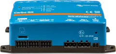 Cerbo GXSystem control centre and gateway to the VRM portal.
Sources
- Multi RS Solar — ch. 7: troubleshooting and error codes (HTML version, status as of 21 September 2026)victronenergy.com · EN
- Multi RS Solar — ch. 6: display, protections and automatic restartsvictronenergy.com · EN
- Multi RS Solar — ch. 4: battery, PV array, PV isolation (4.7), remote and 2-wire BMSvictronenergy.com · EN
- Multi RS Solar — ch. 3: limitations (3.16)victronenergy.com · EN
- Multi RS Solar — technical datavictronenergy.com · EN
- Inverter RS Smart — ch. 7: error codes (HTML version, status as of 21 September 2026)victronenergy.com · EN
- Inverter RS Smart — ch. 4: battery, remote, 2-wire BMSvictronenergy.com · EN
- Inverter RS Smart — ch. 5: BMS control, Ground relayvictronenergy.com · EN
- Inverter RS Smart — technical datavictronenergy.com · EN