

Off-grid cabin
A house without a shore connection works differently from an installation with the grid behind it: there is nowhere to draw energy from, and December gives roughly five times less energy from a roof at an angle than June (with panels lying flat, even several times less). Below is the full system: MultiPlus-II 48/5000 as inverter/charger, separate SmartSolar MPPT 250/100 controller, 48 V LiFePO₄ battery bank managed by the Lynx Smart BMS and a generator as backup — assembled from Victron manuals and system drawings, together with a balance for Polish conditions.
There is nowhere to draw power from
In a house with a shore connection, an energy store is a convenience — if it runs out, the grid tops it up. In a cabin without the grid, the balance must work out every day, including in November. That is why the design starts with consumption and ends with deciding how many days of autonomy you want and what you will use to cover them when the sun is missing.
- 48 V instead of 12 V. With power in the range of several kilowatts, currents in a 12 V installation would be huge — hence the 48 V battery bank and thinner cables.
- Inverter and controller separately. The MultiPlus-II 48/5000 converts 48 V to 230 V and charges the bank from a generator, while the SmartSolar MPPT 250/100 charges it from the panels. Each unit can be replaced or expanded independently.
- Winter gap. From a roof at an angle, December in Poland gives about five times less energy than June — without a generator or shore connection you then need to cut consumption sharply.
- Everything must be protected. At 48 V and panel voltages up to 250 V, fuses and isolators are chosen for voltage as well as current.
Victron does not publish one drawing of this exact setup. The system combines values from the MultiPlus-II and SmartSolar MPPT manuals with two Victron system drawings: BJE-333A (a cabin with the same 48 V bank and Lynx Smart BMS — hence the battery bank, distribution and control) and BJE-354A (an off-grid installation with MultiPlus-II, MPPT 250/100 controllers and a generator — hence the PV side, controller fuse and generator input).

Panels at an angle
A roof at an angle close to 39° gives in Warsaw about 4.4 kWh per kilowatt in June and 0.85 kWh in December.
10.2 kWh storage
Two Smart LiFePO₄ 25.6 V/200 Ah batteries in series — 48 V and 200 Ah capacity.
5 kVA output
MultiPlus-II 48/5000: 4,000 W continuous power at 25 °C, 3,700 W at 40 °C, 9,000 W peak. Generator charger up to 70 A.
Generator as backup
AC input with a breaker rated at up to 50 A: the generator charges the battery bank and supplies the house at the same time, and the MultiPlus can start it automatically.
How it is connected
Panels through an isolator to the SmartSolar MPPT 250/100 controller, a 48 V battery bank with Lynx Smart BMS and Lynx Distributor, MultiPlus-II 48/5000 with generator on the input and two 230 V circuits, and above all a Cerbo GX with a GX Touch 70 display. Hover over the elements in the diagram or touch them. The diagram is indicative — the devices and protection equipment are shown in the detailed diagram below.
- Panels through the controllerThe array goes through the PV isolator to SmartSolar MPPT 250/100, and the controller charges the battery bank through a 125 A fuse.
- String voltage limitString open-circuit voltage of at most 250 V in the coldest conditions; for the controller to start, panel voltage must be 5 V higher than battery voltage.
- Battery bank protected by BMSTwo Smart LiFePO₄ 25.6 V/200 Ah batteries in series, a 250 A main fuse and a 275 A switch, with Lynx Smart BMS above all.
- Inverter/chargerMultiPlus-II 48/5000 with a 200 A fuse supplies the house and charges the battery bank from the generator.
- Two 230 V circuitsAC-out-1 works all the time, AC-out-2 only when the generator is running. Each has its own RCD.
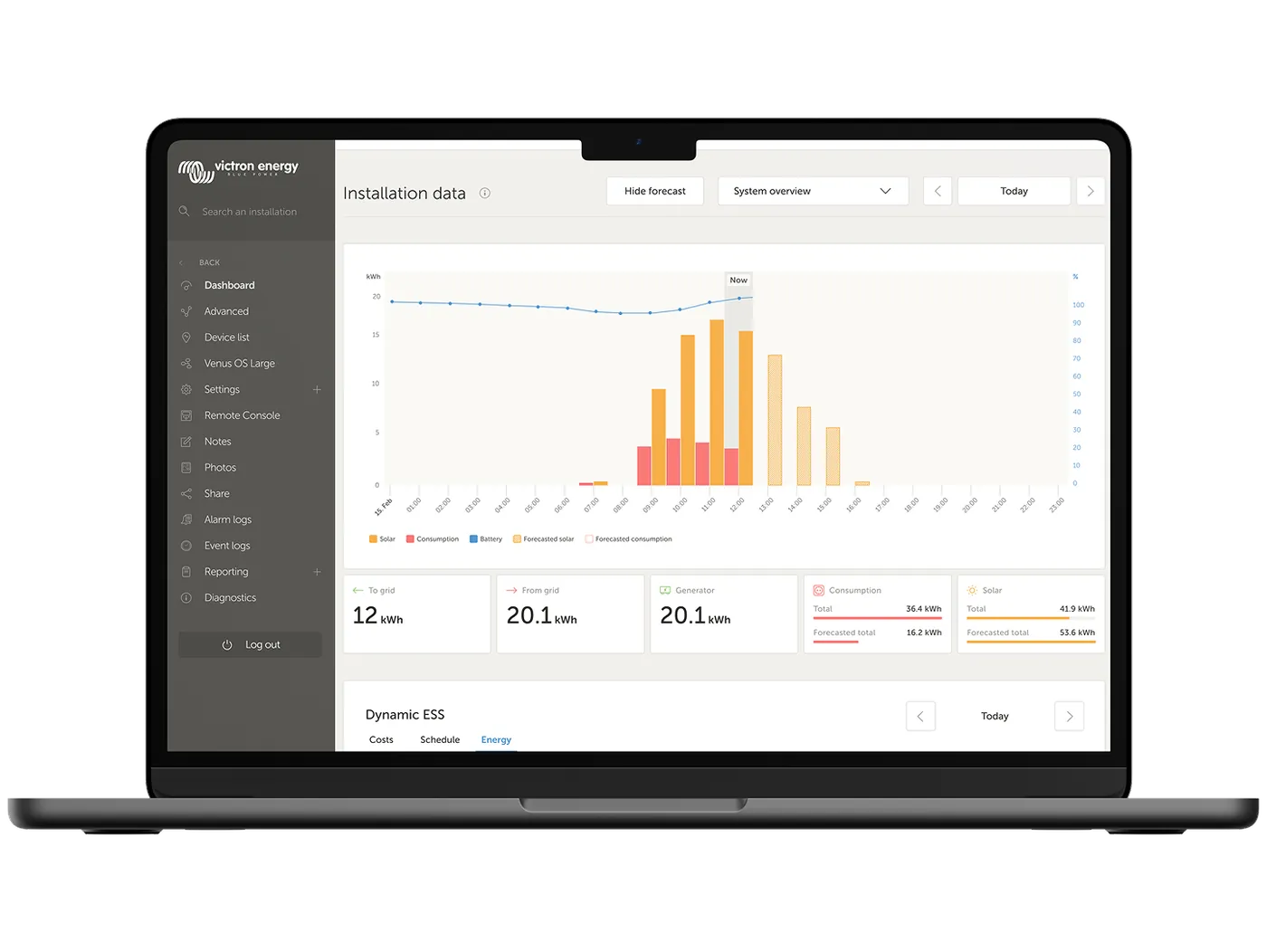
- Monitoring and remote accessCerbo GX controls the MultiPlus and controller via DVCC and sends data to the VRM portal — via Ethernet or an LTE modem.
Distribution boards, protections and DC side
The same cabin in single-line view: generator input, PV side with string breakers and surge protection, battery bank with fuse and switch, Lynx, RCDs on both outputs and control connections. The values come from the MultiPlus-II and SmartSolar MPPT manuals and from drawings BJE-333A and BJE-354A; the manufacturer treats the AC distribution boards in the drawings as examples — always check local requirements as well.
- AC inputGenerator through a breaker, max. 50 A, with surge protection; input current limit set for the generator.
- PV inputStrings of 3–4 modules, 15 A DC breaker per string, PV isolator and type 2 surge protection matched to 250 V.
- ControllerSmartSolar MPPT 250/100 with a 125 A fuse in the Lynx Distributor.
- Battery bank and its protection2 × 25.6 V/200 Ah, MEGA 250 A, 275 A switch, Lynx Smart BMS 500 with shunt.
- Inverter and outputsMultiPlus-II with a 200 A fuse (70 mm² up to 5 m); AC-out-1 and AC-out-2 — each with a 30 mA RCD and circuit breakers.
- ControlCerbo GX with AUX BMS via 1 A, VE.Bus to the MultiPlus, VE.Can with terminators, pre-alarm buzzer and BMS switch.
Layout in a cabin
There is more space in a building than in a campervan or on a yacht, but the rules stay the same: the battery bank low down and warm, the inverter close to the batteries, fuses in one place.
Pan the drawing sideways to see the whole cabin.
- 1
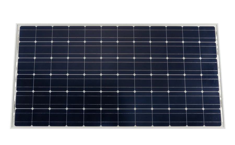 Panels on the roofOn the cabin roof the panels sit at an angle, so they work much better than flat on a campervan. The cable from the array runs through the loft straight to the plant room.
 - 2PV isolatorThe first device after the roof cable enters: a PV isolator with type 2 surge protection and 15 A DC breakers for the strings. The array must be able to be isolated without going onto the roof.
- 3
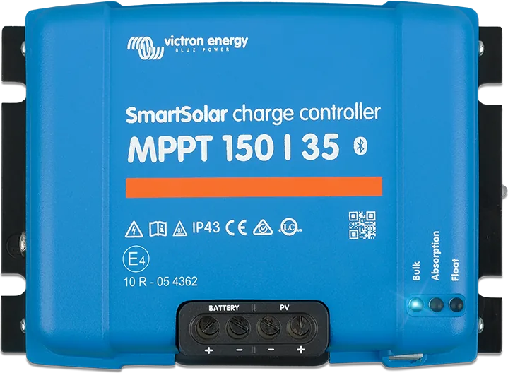 SmartSolar MPPT 250/100A standard solar charge controller on the wall below the isolator and close to the Lynx, so the cable to the batteries is short. It delivers full power up to 40 °C ambient.
 - 4
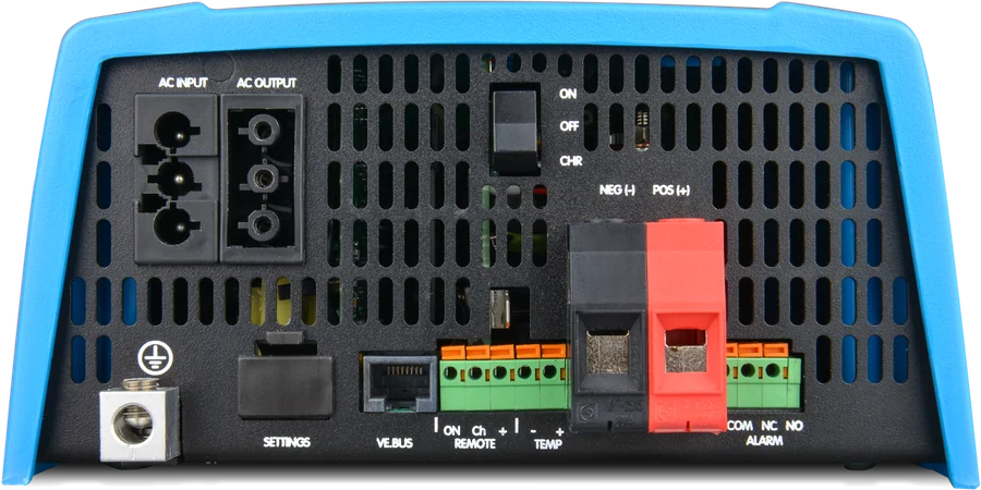
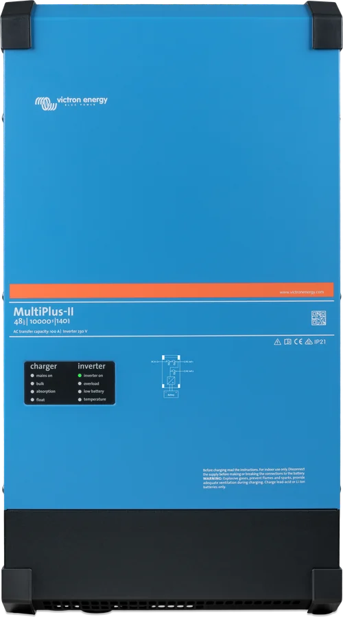 MultiPlus-II 48/5000On a solid wall, in a dry and ventilated place, as close to the batteries as possible. The inside must remain accessible, and there must be no flammable materials nearby.
 - 5
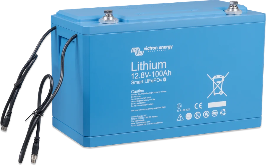 48 V / 200 Ah batteriesThe battery bank stands on the plant room floor — low, dry and at positive temperatures. The BMS cables are linked in a chain to the Lynx Smart BMS.
 - 6
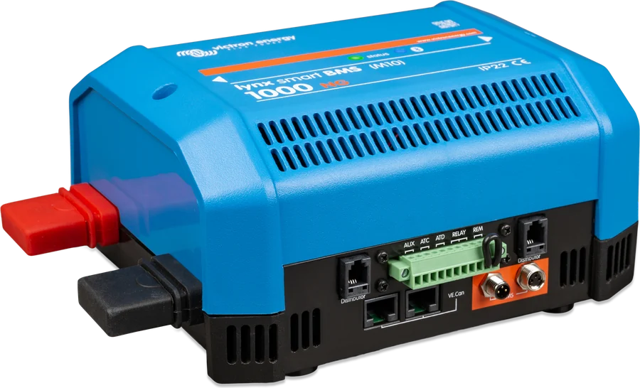 Lynx Smart BMS and DistributorAll DC cables meet here: the battery bank through a 250 A fuse and 275 A switch, the MultiPlus through 200 A, and the controller through 125 A.
 - 7
 AC distribution boardIn the plant room, below the MultiPlus: generator input with breaker and surge protection, then the house circuits with RCDs on AC-out-1 and AC-out-2.
 - 8
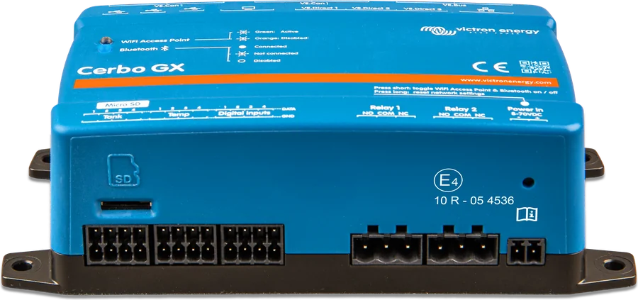 Cerbo GX and displayCerbo with a GX Touch 70 display above the MultiPlus. It controls the MultiPlus and the controller via DVCC and sends data to VRM. Powered from the AUX BMS output through a 1 A fuse.
 - 9
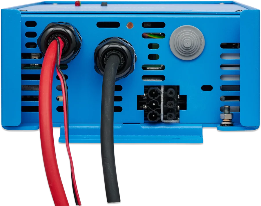 GeneratorOutside, with a cable to the distribution board in the plant room. The MultiPlus charges the bank from it with up to 70 A and can also start it automatically.
How many panels and how many batteries
You size it month by month, not by annual average — because in an off-grid cabin what matters is the worst month when you are actually living there. Below is the yield for Warsaw, for an array at the optimum angle (39°), from PVGIS data also used in our calculator.
To convert energy into bank capacity, divide watt-hours by system voltage: 10 kWh at 48 V is about 208 Ah. The bank in this diagram — 48 V and 200 Ah — has about 10.2 kWh and falls within the 200–800 Ah range recommended by the MultiPlus-II manual for the 48/5000 model.
Add the inverter to the house consumption: the MultiPlus-II 48/5000 draws 18 W at no load, which is about 0.4 kWh per day. In AES mode it is 12 W, and in Search mode — when nothing is switched on — 4 W.
| Month | Yield from 1 kWp (Warsaw, 39°) | Array 3 kWp per day | Array 5 kWp per day |
|---|---|---|---|
| June | 4.43 kWh | approx. 13.3 kWh | approx. 22.2 kWh |
| April | 3.96 kWh | approx. 11.9 kWh | approx. 19.8 kWh |
| September | 3.49 kWh | approx. 10.5 kWh | approx. 17.5 kWh |
| October | 2.36 kWh | approx. 7.1 kWh | approx. 11.8 kWh |
| November | 1.14 kWh | approx. 3.4 kWh | approx. 5.7 kWh |
| December | 0.85 kWh | approx. 2.6 kWh | approx. 4.3 kWh |
PVGIS 5.3 data (SARAH3 database, 2005–2023), installation at optimum tilt, with 14% system losses. Both arrays in the table fit within the 5,800 W that the SmartSolar MPPT 250/100 supports at 48 V. In winter you must also allow for shorter days and snow on the panels — that is why year-round cabins are planned with a generator or with consumption cut back sharply in December and January.
Panels and MPPT controller
The panels charge the bank through a standard SmartSolar MPPT 250/100 controller — a separate device next to the MultiPlus. The controller has its own limits, which cannot be bypassed:
- Open-circuit voltage up to 250 V. This is the absolute maximum in the coldest conditions; for start-up and operation the datasheet gives 245 V. A surge will damage the controller, so the string is sized for frost, not for 25 °C from the nameplate. Drawing BJE-354A shows strings of 3–4 modules.
- Start voltage. The panel voltage must be at least 5 V higher than the battery voltage for the controller to start charging; after that, 1 V more is enough.
- Power and current. At 48 V the array can be up to 5,800 W — above that the controller will limit power itself. Array short-circuit current must be no more than 70 A, and no more than 30 A per MC4 connector. Higher short-circuit current can damage the controller.
- Earthing. The positive and negative of the array must not be earthed; only the panel frame is earthed, which reduces the effects of lightning strikes. The installation negative is connected to earth at one point, preferably by the battery.
A PV isolator sized to the array is mandatory, and the surge protection device must match the controller’s 250 V range. String work must be carried out by a qualified person.
In the MPPT calculator you enter the panel parameters and see whether the string stays within the controller’s voltage and current limits.
48 V bank and its protection
The battery bank consists of two Smart LiFePO₄ 25.6 V/200 Ah batteries connected in series — 48 V and 200 Ah. It is monitored by Lynx Smart BMS with a built-in shunt, and the circuits are distributed by a Lynx Distributor.
- Charge current limit. The battery manufacturer recommends charging at about 0.5C — for this bank up to 100 A. The controller (100 A) and the MultiPlus from the generator (70 A) can together supply 170 A, so the limit is set in DVCC in Cerbo GX.
- Digital control. The MultiPlus and controller are controlled by the Cerbo GX (DVCC), so the ATC and ATD contacts are not needed in this arrangement.
- Pre-alarm. A buzzer connected via the BMS relay sounds when a cell voltage is approaching an undervoltage condition and gives you about 30 seconds to react before the BMS disconnects the loads.
- BMS switch and VE.Can. Instead of a link on the Remote terminals, you can fit a small switch — the manufacturer recommends placing it out of children’s reach. The VE.Can network is connected with standard RJ45 cables, and terminators are fitted to the free sockets.
Two circuits and earthing
The MultiPlus provides two circuits. AC-out-1 is always powered — from the inverter or, when the generator is running, via the AC input. AC-out-2 is live only when external power is present: it disconnects immediately when running from the battery and comes back about 2 minutes after voltage appears at the input. This is a good place for loads that do not make sense on battery power: a boiler, heater or workshop.
The MultiPlus has an earth relay: when there is no input supply, it connects the output neutral to the enclosure, and before the generator is switched on it opens — this means RCDs work in both modes. The enclosure must have a continuous earth. In a fixed installation this is provided by the AC input protective conductor, but in a cabin where the generator is connected only occasionally, the enclosure must be earthed separately.
- AC-out-1: RCD and protection sized to the load. With PowerAssist, the output current is the sum of the input current and the inverter current — cables and protection are sized for that total.
- AC-out-2: up to 32 A, own RCD.
- Type A RCDs are sufficient — the transformer in the MultiPlus rules out DC at the AC terminals.
Distribution boards, RCDs, earthing and neutral-to-earth bonding in the building are tasks that must be carried out and signed off by a qualified person. Local regulations may require a different arrangement from the one shown in the diagram.
Generator, expansion and grid inverter
Generator on the AC input
Through a switch rated at up to 50 A (lower for a smaller generator) and an overvoltage protector. The input current limit is set to suit the generator — the MultiPlus takes only the surplus over the loads for charging, and at peaks it adds power from the battery (PowerAssist). A programmable relay can start and stop the generator.
charge up to 70 ASecond MPPT solar charge controller
When the array exceeds the capacity of one controller, the second array is connected through another SmartSolar MPPT to a free position in the Lynx Distributor. VE.Can controllers work in parallel in synchronisation — up to 25 units.
free positions in the LynxPV inverter on the output (AC coupling)
A grid inverter on the AC-out-1 of the MultiPlus is controlled by frequency shifting. A factor of 1.0 applies — maximum 4000 W — and a minimum of 4.8 kWh of lithium battery per 1.5 kWp, which means with 10.2 kWh up to 3.2 kWp. In an off-grid installation, Victron also requires an MPPT solar charge controller.
up to 3.2 kWpWith a grid inverter on the output, the MultiPlus needs the PV Inverter Support assistant — without the correct frequency settings, the battery bank may be overcharged. Details are in Victron’s “AC-coupling and the Factor 1.0 rule” document.
Key values
| Location | Value | Source |
|---|---|---|
| DC cables for the MultiPlus-II 48/5000 | 70 mm² for battery–MultiPlus distance 0–5 m, 120 mm² for 5–10 m (per pole) | MultiPlus-II manual |
| MultiPlus fuse | 200 A; recommended battery capacity 200–800 Ah | MultiPlus-II manual |
| MPPT 250/100 controller fuse | controller manual: 120–140 A; in the diagram 125 A in the Lynx Distributor; battery terminals up to 35 mm² | MPPT manual, drawing BJE-354A |
| Main battery fuse | 250 A in a MEGA fuse holder, before the 275 A main switch | drawing BJE-333A (same bank) |
| AC input | fuse or circuit breaker up to 50 A (5 kVA model), lower for a weaker source; through current 50 A; input current limit set to suit the generator | MultiPlus-II manual |
| AC-out-1 | RCD and protection sized to the load; type A is sufficient | MultiPlus-II manual |
| AC-out-2 | up to 32 A, voltage only when AC input is powered, return after about 2 minutes; own RCD | MultiPlus-II manual |
| Enclosure earthing | continuous; in a fixed installation via the AC input protective conductor, otherwise the enclosure is earthed separately | MultiPlus-II manual |
| PV side | up to 5800 W at 48 V; open-circuit voltage up to 250 V in the coldest conditions; short-circuit current up to 70 A; 15 A DC switch for each string, PV isolator and type 2 overvoltage protector | MPPT datasheet, drawing BJE-354A |
| Control circuits | Cerbo GX from the AUX BMS output via a 1 A fuse, pre-alarm buzzer via 0.2 A | drawing BJE-333A |
| Output distribution boards | on AC-out-1 and AC-out-2 a 30 mA RCD with switch, then circuit breakers (three each in the drawing) | drawing BJE-333A |
At 48 V, one rule that is easy to forget applies: every fuse must have a rated voltage at least as high as the installation voltage. DC fuse links are often intended for 12 and 24 V and are not suitable for 48 V, even if the current rating is correct — in drawing BJE-354A all MEGA fuse links are the 58 V version. In the parts list for drawing BJE-333A, MEGA fuse links in the 32 V version are listed, although on the graphic itself the main fuse is marked “58V” — for a 48 V battery bank choose the 58 V version.
The rest of the rules are the same as for any DC installation: voltage drop below 2.5%, cross-section sized for the current and the total length of the positive and negative cable, flexible fine-strand cables. At 48 V, the same power means four times lower current than at 12 V — hence sensible cable sizes despite 5 kVA of power.
Calculate the cross-sections for the other circuits in the cable and fuse calculator — you enter the current, voltage and length, and you get the cross-section and fuse size.
What to watch out for in this setup
The MultiPlus hangs on a solid wall in a dry, well-ventilated place, as close to the battery as possible — short cables mean lower losses. The inside must remain accessible, and there must be no flammable materials nearby.
The MultiPlus-II manual requires a means of disconnecting both the AC and DC circuits. A circuit breaker can fulfil this role; with fuses, a separate isolator is needed between the source and the fuse.
At each Lynx Distributor position, connect the negative cable first, then the positive. Close the free VE.Can sockets in the BMS and controller with terminators — without them, communication can be unstable.
- Keep the battery warm. LiFePO₄ does not accept charging below +5 °C — in a seasonal cabin, keep the storage inside, not in an unheated annex.
- PV isolator within reach. It must be possible to isolate the array before service work, without going onto the roof.
- Controller out of the heat. SmartSolar MPPT delivers full power up to 40 °C ambient — do not mount it in a hot loft.
- Label the circuits. Stickers by the fuses and distribution board save time every time there is a fault.
Seasonal cottage versus year-round cottage
- December is one fifth of June. The same 3 kWp array gives about 13 kWh per day in June and about 2.6 kWh in December — the winter plan must take that into account.
- Snow and frost can reduce production to zero for several days. In a year-round cottage, that is a reason for a generator or for a larger PV array than the July balance suggests.
- Frost raises panel voltage. The array’s highest open-circuit voltage is on a frosty, sunny morning — that is when the string must not exceed 250 V.
- Closing the season? Charge the battery bank, keep the BMS and Cerbo powered, and set the heating so that the temperature in the battery room does not fall below freezing. A switched-off MultiPlus then does not waste 18 W.
- Remote monitoring. Cerbo with an LTE modem shows battery bank state and alarms in VRM — for a cottage visited once every few weeks, that is essential.
Eight mistakes that cost the most
In an off-grid system, every sizing mistake is visible straight away — as a discharged battery bank or a shut-down inverter.
Sizing for July
An installation sized for summer sun stops coping in November. You size the system for the month when you actually live there, not for the annual average.
String above 250 V in frost
Open-circuit voltage rises in frost. A string sized for 25 °C can exceed 250 V in winter and damage the controller.
Without a charge current limit
The controller and MultiPlus from the generator together deliver up to 170 A, and the battery bank accepts the recommended 100 A. The limit is set in DVCC in Cerbo GX.
Fuse for the wrong voltage
At 48 V, an insert intended for 12–24 V may not clear the arc. The fuse’s rated voltage is chosen together with the current — MEGA in the 58 V version.
Battery in an unheated annex
Below +5 °C, LiFePO₄ does not accept charging. The storage is kept in the heated part of the building.
Enclosure without earthing
When the generator is not connected, the AC input protective conductor does not earth the MultiPlus. The enclosure is earthed separately, and each output has an RCD.
PV inverter without frequency settings
In an AC-coupled system, the grid-tie inverter must reduce power as frequency rises, and the MultiPlus needs the PV Inverter Support assistant.
Cottage without remote monitoring
Cerbo with VRM access shows battery bank state and alarms when nobody is on site — in an off-grid installation, that is the cheapest insurance.
Common questions about an off-grid installation
How many panels does a cottage without grid connection need?
Enough to cover consumption in the worst month when you live there. In Warsaw, a 3 kWp array at a 39° tilt gives about 13.3 kWh per day in June, 7.1 kWh in October and 2.6 kWh in December (PVGIS data with 14% losses). That is why year-round cottages use a larger array than a summer balance suggests — one 250/100 controller will handle up to 5,800 W at 48 V.
Why 48 V, not 12 V?
Because at a power level of several kilowatts, the current in a 12 V system would be huge and the cables very thick. At 48 V, the same power means four times less current.
Why a separate controller, not an inverter with built-in MPPT?
A standard SmartSolar MPPT and a MultiPlus-II are two independent devices: you can replace the controller, add a second one to a free position in Lynx, or move it closer to the panels, and the MultiPlus keeps working. In an off-grid Victron system, a MPPT solar charge controller is required anyway if a grid-tie inverter is added on the output.
What panel voltage may be connected?
The string open-circuit voltage must be no more than 250 V in the coldest conditions, and the datasheet gives 245 V for operation. At the same time, the panel voltage must be at least 5 V above battery voltage for the controller to start. Calculate Voc for the lowest expected temperature, because frost raises panel voltage.
How much energy does the battery bank in this diagram hold?
Two Smart LiFePO₄ 25.6 V/200 Ah batteries in series give 48 V and 200 Ah, which is about 10.2 kWh. How much you can really use depends on the set thresholds and the reserve you want to keep for cloudy days.
Can I add a generator later?
Yes. The MultiPlus AC input takes a generator through a switch rated up to 50 A. You only need to prepare an input distribution board with surge protection; the input current limit is set to suit the generator, and the MultiPlus programmable relay can start it.
Can I connect a standard grid-tie PV inverter?
Yes, on the AC output side (AC coupling). The MultiPlus then regulates its power by shifting frequency; factor 1.0 applies (max. 4,000 W) and a minimum battery capacity is required — with 10.2 kWh, that is 3.2 kWp. The PV Inverter Support assistant is needed.
What about the installation in winter when the cottage stands empty?
Charge the battery bank, keep the BMS and Cerbo powered, and make sure the temperature in the battery room does not fall below freezing — below +5 °C charging will be suspended anyway. Remote monitoring via VRM lets you respond without travelling there.
Devices in this setup
 MultiPlus-IIInverter/charger with UPS function: pure 230 V sine wave, PowerAssist supports a weak shore connection.
 SmartSolar MPPT 150 and 250 V35–100 A controllers for higher panel voltages: 150 V and 250 V, Tr, MC4 and VE.Can versions.
 LiFePO4 Smart 12,8/25,6 VLithium iron phosphate batteries with Bluetooth — work only with an external BMS.
 Lynx Smart BMS / NGBMS with contactor and current measurement for Smart LiFePO4 or Lithium NG banks.
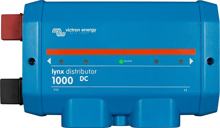
 Lynx DistributorModular 1000 A DC busbars: fused distribution with MEGA fuses and monitoring, battery connection, Class-T fuses.
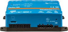 Cerbo GXSystem control centre and gateway to the VRM portal.
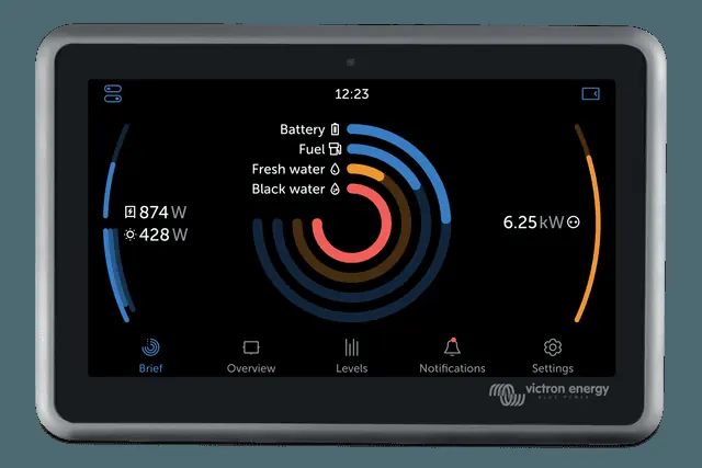
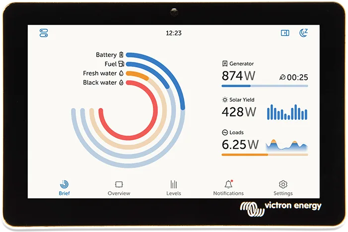
 GX Touch 50/70Optional 5- or 7-inch display for Cerbo GX: system overview, settings, surface or flush mounting.
What next
- Energy balance calculator — consumption, battery and panels for 16 Polish citiestool
- MPPT sizing calculator — does the panel string stay within the limits?tool
- MPPT controller not charging — step-by-step troubleshootingsupport
- Home with energy storage (ESS) — when the building has a grid connectiondiagram
Manufacturer documentation
- MultiPlus-II 230V — manual: installation, DC cables and fuses, AC wiring, earth relay, PowerControl and PowerAssist, technical datavictronenergy.com · PDF · EN
- SmartSolar MPPT 250/70 to 250/100 VE.Can — datasheet: PV power, voltages, short-circuit current, operating temperaturevictronenergy.com · PDF · EN
- SmartSolar MPPT VE.Can — manual: battery fuse, PV array configuration, earthingvictronenergy.com · EN
- Manual & Drawing BJE-354A (off-grid installation with MultiPlus-II, MPPT 250/100 and generator) — PV side, controller fuse, 58 V inserts, generator inputvictronenergy.com · PDF · EN
- Manual & Drawing BJE-333A (cottage with Multi RS Solar, Smart LiFePO₄ 48 V 200 Ah, Lynx Smart BMS, Cerbo GX Touch 70) — battery bank, main fuse, output distribution boards, controlvictronenergy.com · PDF · EN
- AC coupling and the Factor 1.0 rule — PV inverter on the output, minimum battery capacity, MPPT requirement in an off-grid systemvictronenergy.com · EN
- Off-grid system booklet — design principles for off-grid systemsvictronenergy.com · PDF · EN
- PVGIS 5.3 (JRC, European Commission) — solar irradiation data used in the yield tableec.europa.eu
Content checked against Victron Energy documentation (datasheets and manuals) — as of 22 September 2026. Report a content error · Revision log