
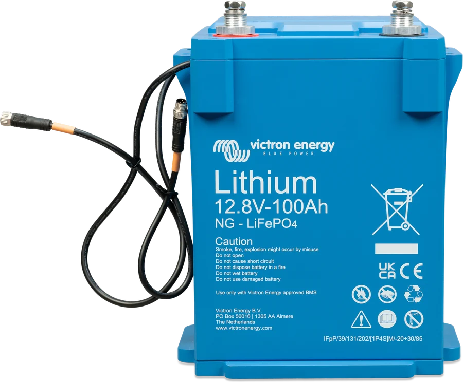
01Series or parallel
Connected batteries form a bank. According to “Wiring Unlimited”, a series connection increases voltage, a parallel connection increases capacity, and a series-parallel connection increases both.
| Connection | What changes | Example with two 12.8 V/200 Ah batteries |
|---|---|---|
| In series (positive of one to negative of the next) | voltage increases, capacity stays the same | 25.6 V · 200 Ah |
| In parallel (positives together, negatives together) | capacity increases, voltage stays the same | 12.8 V · 400 Ah |
| Series-parallel | voltage and capacity increase | e.g. 4 batteries: 25.6 V · 400 Ah |
The bank’s energy is the same in both cases — here 2 × 2.56 kWh. The choice of arrangement depends on the system voltage: a 12 V bank is built in parallel, while 24 and 48 V systems use higher-voltage batteries or series connections.
02How many batteries in one bank
| Battery | Maximum in the system | Maximum in series | Largest bank |
|---|---|---|---|
| Lithium NG 12.8 V i 25.6 V | 50 batteries | 4 × 12.8 V or 2 × 25.6 V | 192 kWh at 12 V, 384 kWh with 25.6 V batteries |
| Lithium NG 51.2 V | 25 batteries (parallel only) | — | 128 kWh |
| Lithium Smart 12.8 V i 25.6 V | 20 batteries | 4 × 12.8 V or 2 × 25.6 V | 84 kWh at 12 V, 102 kWh at 24 and 48 V |
The battery count limits apply regardless of BMS model. A larger Lithium NG store can be built from several banks with their own BMS: the Lynx Smart BMS NG datasheet states that up to 5 such BMS units can operate in parallel.
48 V installation: with Lithium NG batteries this is 51.2 V in parallel, 2 × 25.6 V in series or 4 × 12.8 V in series. The VE.Bus BMS V2 datasheet recommends using as few batteries in series as possible — a 24 V system is best built from 25.6 V batteries, and a 48 V system from two 25.6 V batteries. Four 12.8 V batteries in series will also work, but they require more time for periodic cell balancing.
03Parallel bank — how to connect
The most common mistake according to “Wiring Unlimited”: batteries connected in parallel, with the installation connected to one end of the bank. Then current from the more distant batteries flows through the extra connecting cables, so the nearest battery is charged and discharged more heavily — and wears out first. The book shows the scale: a 35 mm² cable 20 cm long with terminations is about 1.5 mΩ, while the internal resistance of a battery is usually 3–10 mΩ — the cables are far from negligible.
- Fuse on each batteryPositive of each battery through its own fuse to the positive busbar.
- DiagonallyPositive cable to the installation from one end of the bank, negative from the other.
- System cable cross-sectionBattery cable cross-section times the number of batteries (strings).
- Main fuseOn the main positive cable to the bank.
- BMS cablesIn a chain through all batteries; the first and last to the BMS.
Rules from the Lithium NG manual (and identical in the Lithium Smart manual):
- Fuse on the positive of each battery. All battery connections must be protected.
- System cables diagonally — so that the current path through each battery is the same.
- System cable cross-section must be equal to the battery cable cross-section multiplied by the number of batteries (strings).
- Fuse on the main positive cable to the bank.
“Wiring Unlimited” gives four correct ways to connect batteries in parallel: busbars, the positive and negative posts with cables of equal length to each battery, connection in the middle of the bank with cables of the same thickness, and diagonal connection. On the last of these, the book says frankly: it is simple and effective, but not ideal — the currents of individual batteries may differ slightly.
04Series and series-parallel bank
- Charge each battery separately first. Batteries leave the factory charged to roughly half, but after transport and storage their state of charge may differ. The balancing system in the battery corrects only small differences, and only between the cells of the same battery. That is why, before connecting in series, each battery is charged separately to full and cell balance — with a charger controlled by the BMS. As a whole, you may charge only one battery or batteries connected in parallel.
- Fuse on the positive of each series string and on the main positive cable, system cables diagonally, system cable cross-section = string cable cross-section × number of strings.
- Do not connect the midpoints of strings and do not connect anything to them. “Wiring Unlimited” describes midpoint connection as a balancing method — but in the chapter on lead-acid banks. For Lithium NG and Lithium Smart batteries, the manuals prohibit this.
Batteries in series are also the most demanding when expanding the bank — see adding and replacing batteries.
05Fuses: the rule and Victron diagrams
The Lithium NG and Lithium Smart manuals say this: system current, and therefore the fuse rating, should not exceed the battery’s maximum continuous current. Choose the fuse according to the lowest of three values — cable current rating, battery current and system current. Victron system diagrams show these values:
| Victron diagram | Battery | Battery fuse | Battery current according to the documentation |
|---|---|---|---|
| BJE-300D (van, VE.Bus BMS V2) | 2 × Lithium Smart 12.8 V/200 Ah | ANL 300 A | max. continuous 400 A, recommended ≤ 200 A |
| BJE-351A (Quattro-II 24 V) | 3 × Lithium NG 25.6 V/200 Ah | Class T 350 A | max. continuous 200 A, 400 A for 10 s |
| BJE-367A (two MultiPlus-II 24 V) | Lithium NG 25.6 V/300 Ah | Class T 350 A | max. continuous 300 A, 600 A for 10 s |
Discrepancy: with Lithium NG batteries, the diagrams use Class T 350 A fuses, which is above the battery’s maximum continuous current, which according to the manual sets the upper fuse limit. With Lithium Smart 200 Ah, the value in the diagram (300 A) is below the continuous current of 400 A. Victron diagrams are examples — the fuse rating in a specific installation is chosen and confirmed by the designer. More on cable cross-sections and breaking capacity: cable cross-sections and DC fuses.
Example implementation from the Lynx Smart BMS NG datasheet: Lithium NG batteries connected in parallel through a separate Lynx Distributor with a fuse on each battery, then Lynx Smart BMS NG and a second Lynx Distributor for loads and chargers. Such a setup has a home with energy storage (six 51.2 V batteries).
06Which BMS
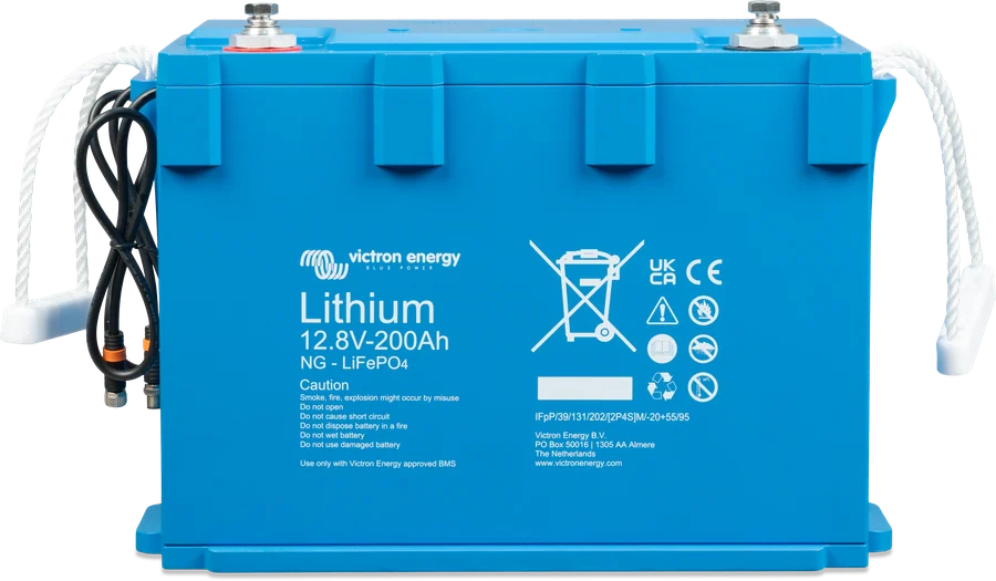
Lithium NG and Lithium Smart batteries measure cell voltages and temperature themselves, but they do not disconnect current — the BMS does that by switching off loads and chargers. The BMS cables of all batteries are connected in a chain, and the first and last are connected to the BMS; the order of the batteries does not matter. Lithium NG batteries work only with BMS units marked “NG”.
| Batteries | BMS | Typical use according to the manual |
|---|---|---|
| Lithium NG | smallBMS NG | small systems without an inverter/charger |
| VE.Bus BMS NG | systems with a VE.Bus inverter/charger (MultiPlus, Quattro); with MultiPlus-II and Quattro-II, the supplied grid detector is not needed | |
| Lynx Smart BMS NG 500 A / 1000 A | larger systems with digital integration or when a built-in safety contactor is needed; also with an inverter/charger if there is a GX device | |
| Lithium Smart | smallBMS | small systems without an inverter/charger |
| VE.Bus BMS V2 | systems with an inverter/charger — as in a workshop van | |
| Lynx Smart BMS 500 A / 1000 A | larger systems with digital integration or when a built-in contactor is needed | |
| Smart BMS CL 12/100, Smart BMS 12/200 | 12 V only, relatively small systems with an alternator (and DC loads) |
When the BMS blocks charging or loads: “BMS has shut down charging”.
07Adding and replacing batteries
It is best when all batteries in the bank have the same capacity, age and model. However, the manuals allow expansion and replacement of a single battery:
| Bank type | Different capacities? | Different age? |
|---|---|---|
| Parallel | yes | yes |
| Series | no — the same capacity and the same part number | yes, difference of up to 3 years |
| Series-parallel, within a string | no | yes, difference of up to 3 years |
| Series-parallel, when an entire string is added or replaced | yes | yes |
Why series is so demanding: the manual gives the example of a 50 Ah battery in series with a 100 Ah battery. The string initially has 50 Ah, but over time the batteries drift apart — with a 10 Ah difference, 40 Ah remains. During charging, the cells of the fuller battery receive too high a voltage, and the BMS keeps intervening: the emptier battery is discharged too deeply, the fuller battery overcharged.
With Lithium NG batteries added later, the battery firmware updates itself through the BMS.
Devices in this guide
 Lithium NGVictron’s new generation of LiFePO4 batteries: 12.8/25.6/51.2 V, IP65, built-in current measurement — only with BMS NG.
 LiFePO4 Smart 12,8/25,6 VLithium iron phosphate batteries with Bluetooth — work only with an external BMS.
 Lynx Smart BMS / NGBMS with contactor and current measurement for Smart LiFePO4 or Lithium NG banks.
 VE.Bus BMS NGBMS for Lithium NG batteries in a system with MultiPlus or Quattro — Bluetooth, SoC on GX, discharge floor.
 smallBMS NGSimple BMS for Lithium NG batteries without VE.Bus — controls chargers and loads via outputs, with Bluetooth.
 VE.Bus BMS V2BMS for Lithium Smart batteries in a system with MultiPlus or Quattro — controls the inverter, chargers and loads.
 Lynx DistributorModular 1000 A DC busbars: fused distribution with MEGA fuses and monitoring, battery connection, Class-T fuses.
Sources
- Lithium NG — manual: sections 3.1 (number of batteries), 3.3 (BMS models), 4.3 (charging before connection), 4.5 (cables, fuses, series and parallel), 4.6 (BMS cables)victronenergy.com · EN
- Lithium NG 12.8/25.6/51.2 V — datasheet: battery currents, number of batteries per BMSvictronenergy.com · PDF · EN
- Lithium Smart — manual (rev 21): number of batteries, BMS models, connection, technical datavictronenergy.com · PDF · EN
- VE.Bus BMS V2 — datasheet: up to 20 batteries, recommendation for 24 and 48 V banksvictronenergy.com · PDF · EN
- Lynx Smart BMS NG — datasheet: system example with Lynx Distributor on the battery side, up to 5 BMS in parallelvictronenergy.com · PDF · EN
- Wiring Unlimited (rev 04) — section 3: connecting batteries in a bank, parallel bank, midpoints in lead-acid banksvictronenergy.com · PDF · EN
- Manual & Drawing BJE-300D — Lithium Smart 12.8 V/200 Ah with ANL 300 A fusesvictronenergy.com · PDF · EN
- Drawing BJE-351A — 3 × Lithium NG 25.6 V/200 Ah with 350 A Class T fusesvictronenergy.com · PDF · EN
- Drawing BJE-367A — Lithium NG 25.6 V/300 Ah with 350 A Class T fusesvictronenergy.com · PDF · EN