

Workshop van and service vehicle
A mobile workshop needs 230 V for power tools and 12 V for lighting, whether the engine is running or not. Below is a complete 12 V system: MultiPlus-II 12/3000, two Lithium Smart 200 Ah batteries under VE.Bus BMS V2, charging from the alternator through two Orion-Tr Smart units, from the roof through an MPPT 100/50 controller, and from mains at base — with the fuses shown in Victron drawing BJE-300D and the layout in the vehicle.
Four decisions before the build
In a workshop van the system works differently from a motorhome: during the working day, large 230 V loads are switched on briefly between drives. Energy has to be returned to the battery while driving, and in the evening — from mains at base. The system is selected in this order:
- 1. 230 V power. The MultiPlus-II 12/3000 delivers 2,400 W continuous at 25 °C, 2,200 W at 40 °C and 5,500 W peak — for starting power tool motors. This determines the rest of the system.
- 2. Battery. The MultiPlus-II manual recommends a 400–1,200 Ah bank for the 12/3000 model. Here: two Lithium Smart 12.8 V/200 Ah batteries, 400 Ah in total and about 5.1 kWh, under VE.Bus BMS V2.
- 3. Charging while driving. Two isolated Orion-Tr Smart 12/12-30 units provide 60 A in total from the alternator, the MPPT 100/50 controller provides up to 50 A from the roof, and the MultiPlus provides up to 120 A from mains at base.
- 4. Protection and monitoring. VE.Bus BMS V2 switches off the inverter, loads and chargers before the cells leave the safe range. SmartShunt calculates state of charge, and Cerbo GX shows everything on the display and in VRM.
The starting point is Victron drawing BJE-300D (van or small motorhome with VE.Bus BMS V2, MultiPlus-II 3 kVA, 400 Ah, SmartShunt, Smart BatteryProtect 100 A, MPPT 100/50 and two Orion-Tr Smart units) — from it comes the DC side, fuses and control. BJE-300D is the North American version (120 V / 60 Hz), so the 230 V side was taken from the MultiPlus-II 230 V manual and from the European BJE-256B drawing (VE.Bus BMS with a 3 kW 12 V MultiPlus in a vehicle with an alternator). The whole thing is Victron’s “advanced lithium system” from the “Automotive system booklet”.

230 V for tools
2,400 W continuous power and 5,500 W peak. At base, PowerAssist adds battery power to a weak shore connection.
60 A from the alternator
Two isolated Orion-Tr Smart units at 30 A each — isolation protects against interference from the vehicle’s CAN bus.
Battery under BMS control
VE.Bus BMS V2 controls the MultiPlus, DC loads, Orions and, via Cerbo GX, the solar charge controller.
Fleet overview
Cerbo GX sends data to VRM — the state of charge and alarms for each vehicle can be seen from the office.
How it is connected
Energy flow with fuses from drawing BJE-300D: three charging sources, a 400 Ah battery bank with main switch and SmartShunt, Lynx Distributor, MultiPlus-II with 230 V circuits and 12 V loads behind a Smart BatteryProtect. The BMS control signals are on a separate diagram below. Hover over a diagram element or tap it.
- Three charging sourcesPanels via MPPT 100/50 (60 A), alternator via two Orion-Tr Smart (125 A) and mains via the MultiPlus.
- 400 Ah bankTwo Lithium Smart 12.8 V/200 Ah, each with an ANL 300 A fuse, 275 A main switch, negative via SmartShunt.
- Lynx DistributorFour MEGA fuses: 400 A MultiPlus, 125 A Orions, 100 A Smart BatteryProtect, 60 A controller.
- 230 VMultiPlus-II 12/3000: input up to 32 A, workshop sockets on AC-out-1, mains-only circuits on AC-out-2.
- 12 VDC loads behind Smart BatteryProtect 100 A, controlled by the BMS.
- BMS and monitoringVE.Bus BMS V2 connected to the batteries (BTV), MultiPlus and Cerbo GX.
What the VE.Bus BMS V2 controls
The BMS does not carry battery current — it switches devices by signals. Here are all its connections from drawing BJE-300D and the VE.Bus BMS V2 datasheet. Hover over an element to see what happens in an alarm.
- MultiPlus-IIVia VE.Bus: low cell voltage switches off the inverter, overvoltage or wrong temperature — the charger.
- Smart BatteryProtectThe “Load Disconnect” output (1 A) disconnects 12 V loads.
- OrionsThe “Charge Disconnect” output (10 mA) stops alternator charging through isolated remote cables.
- MPPT solar charge controllerSwitched off by Cerbo GX and DVCC based on BMS data.
- Cerbo GX and DMCAt the “Remote panel” port via a splitter; Cerbo powered from GX-Power (1 A).
- Buzzer and switchPre-alarm warns before shutdown; the switch on Remote L–H turns the whole system off.
What Victron documentation actually states
| Location | Value | Source |
|---|---|---|
| Battery fuse | ANL 300 A on the positive, fuse holders connected at the top by a copper busbar | drawing BJE-300D |
| Main switch | 275 A, between the battery busbar and the positive of the Lynx Distributor | drawing BJE-300D |
| Lynx Distributor | MEGA 400 A (MultiPlus), 125 A (Orions), 100 A (Smart BatteryProtect), 60 A (MPPT); MEGA 32 V fuses at 12 V | drawing BJE-300D |
| Orions | at the input and output of each fuse 60 A; outputs on a pair of terminals, then one circuit through 125 A | drawing BJE-300D |
| Small fuses | BMS 2 A, SmartShunt 1 A (power), Aux SmartShunt 1 A at the starter battery, Cerbo 1 A from GX-Power, Smart BatteryProtect negative 300 mA | drawing BJE-300D |
| DC cables for MultiPlus-II 12/3000 | 2 × 50 mm² per pole at up to 5 m, 2 × 70 mm² at 5–10 m; 400 A fuse; recommended battery bank 400–1200 Ah | MultiPlus-II 230 V manual |
| AC input | fuse or isolator rated at up to 32 A (3 kVA model), lower for a weaker hook-up; pass-through current 32 A | MultiPlus-II 230 V manual |
| AC-out-1 and AC-out-2 | RCD and protection on each output, type A is enough; AC-out-2 up to 32 A; with PowerAssist 32 + 13 = 45 A on AC-out-1 | MultiPlus-II 230 V manual |
| MultiPlus-II 12/3000 power | 3000 VA; continuous 2400 W at 25 °C, 2200 W at 40 °C, 1700 W at 65 °C; peak 5500 W; charging up to 120 A | MultiPlus-II 230 V manual |
| BMS outputs | Load Disconnect up to 1 A, Charge Disconnect up to 10 mA, pre-alarm up to 1 A (without short-circuit protection), GX-Power 1 A | VE.Bus BMS V2 datasheet |
| Orion-Tr Smart 12/12-30 isolated | input 8–17 V, output 10–15 V, 360 W (30 A) per unit | drawing BJE-300D |
| MultiPlus enclosure in the vehicle | bonded to the vehicle chassis (cable size one step smaller than the total negative); at least 10 cm of free space all round | MultiPlus-II manual, drawing BJE-300D |
Victron deliberately does not specify cable cross-sections on system drawings — drawing BJE-300D explains that the manufacturer does not know the cable lengths in a specific vehicle. You can calculate the cross-sections for the remaining circuits in the cable and fuse calculator.
Layout in a van
Devices grouped along one side wall of the load space: battery bank low on the floor, Lynx and BMS just above it, inverter beside them. At the front, by the starter battery, only the Orions.
Move the diagram sideways to see the whole vehicle.
- 1
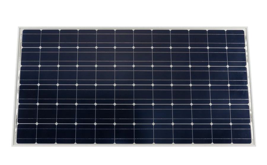 Panels on the roofOn the roof rail or frame of the load space roof, with a sealed cable gland; the cable runs straight down to the PV disconnect.
 - 2
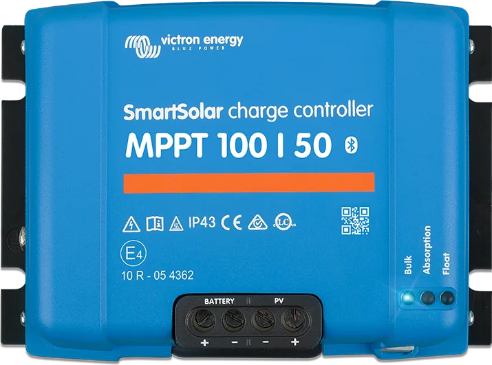 PV disconnect and MPPT 100/50High on the wall, under the roof gland. The run to the battery is short and thick — it carries up to 50 A.
 - 3
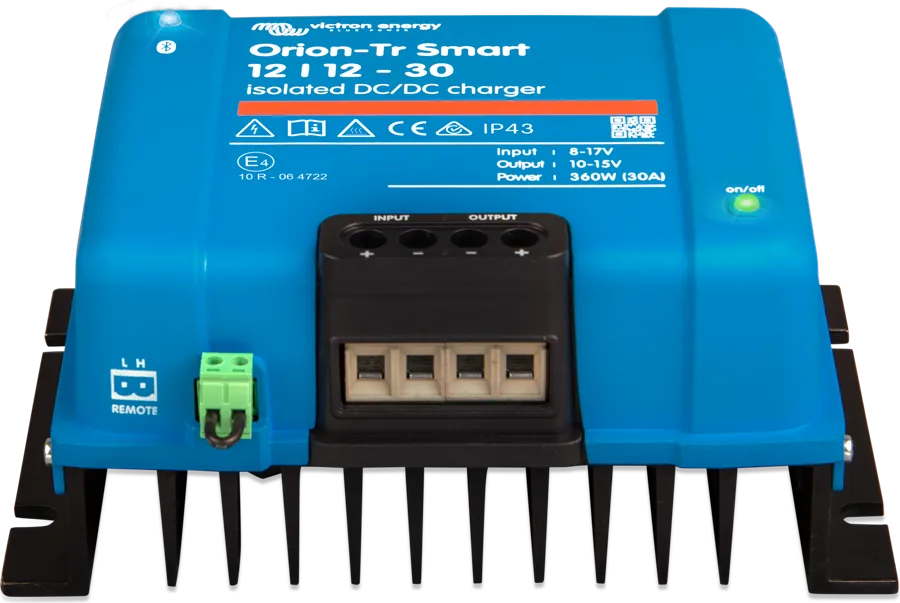 Orions by the starter batteryUnder the cab seat: inputs through 60 A fuses at the battery positive, output through the floor channel to the Lynx.
 - 4
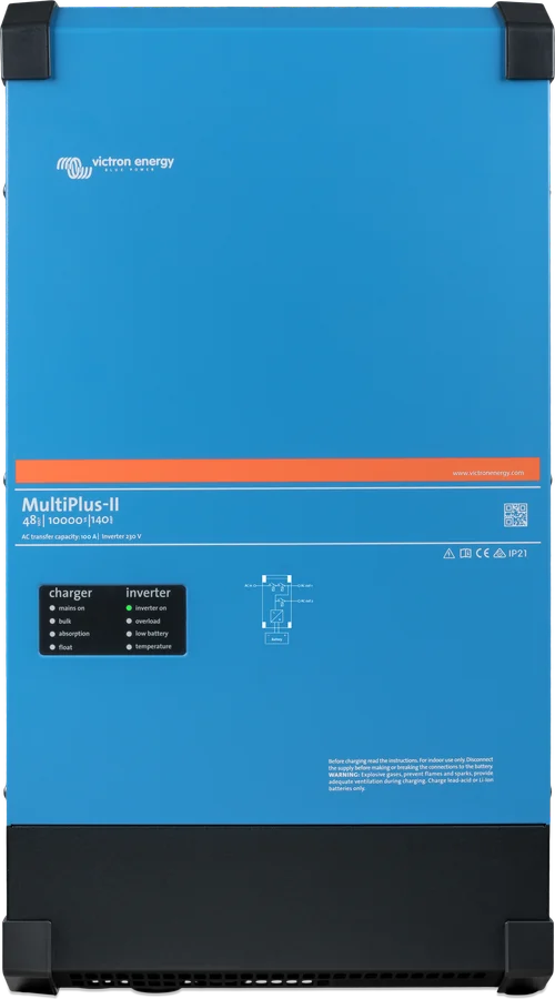 MultiPlus-II 12/3000Next to the Lynx, so the 2 × 50 mm² cables are short. At least 10 cm of free space all round, dry and ventilated.
 - 5
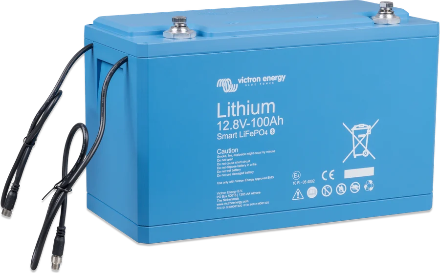 Batteries on the floorMounted low and securely, in the heated part of the conversion — below +5 °C they will not accept charging.
 - 6
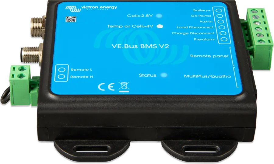 Lynx, BMS and SmartShuntJust above the bank: ANL, 275 A main switch, Lynx Distributor, SmartShunt and BMS in one place, with the main switch to hand.
 - 7
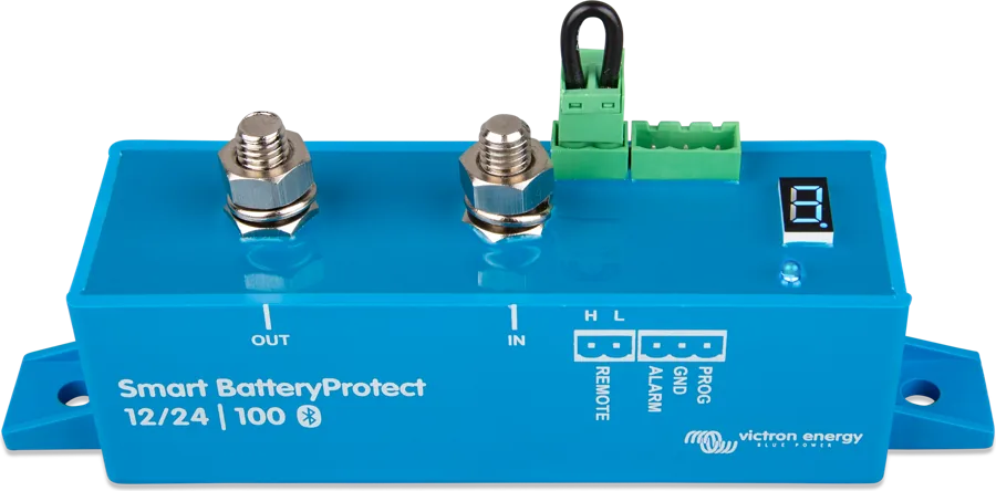 Smart BatteryProtect and DC panelBehind the Lynx, with the 12 V load switch panel; GND wire directly to the negative via a 300 mA fuse.
 - 8230 V work socketsBy the workbench, fed from AC-out-1 through an RCD and breakers — they work on the road and at base.
- 9
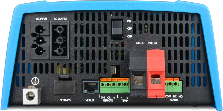 230 V inputExternal inlet on the side of the body, behind it a 32 A breaker and RCD, then the MultiPlus AC input.
 - 10
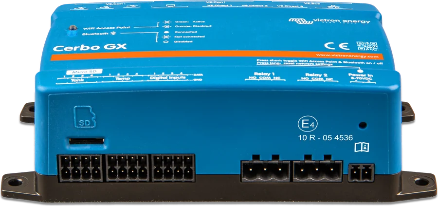 Cerbo GX and displayNext to the Lynx, powered from the GX-Power BMS; GX Touch 50 screen and DMC panel in a visible place.
Working day energy balance
A 400 Ah bank at 12.8 V is about 5.1 kWh. How much of that is left for tools is counted in watt-hours: power times run time, divided by inverter efficiency. The MultiPlus-II 12/3000 has a peak efficiency of 93%, so one hour with a 2,000 W load takes at least 2.15 kWh from the battery — about 42% of the bank.
- Continuous power and heat. 2,400 W at 25 °C, but 2,200 W at 40 °C — in summer, in a hot conversion, the inverter reduces power sooner.
- Tool start-up. Peak power of 5,500 W covers the short start-up current of motors — saws, grinders, compressors. Long running above 2,400 W is an overload.
- No-load consumption. Switched on with no load, the MultiPlus draws 13 W, or about 0.3 kWh per day. In AES mode, 9 W; in Search mode, 3 W.
A larger inverter needs a larger bank: for the MultiPlus-II 12/5000, the manual recommends 600–2,400 Ah, a 600 A fuse and 2 × 95 mm² cables — that is a different scale of installation.
| Source | Charge current | When |
|---|---|---|
| 2 × Orion-Tr Smart 12/12-30 | 60 A (2 × 360 W) | on the road, when the engine is running |
| SmartSolar MPPT 100/50 | up to 50 A | during the day, depending on the sun and field |
| MultiPlus-II (charger) | up to 120 A | at base or from a generator |
One hour of driving through two Orions is about 0.72 kWh (2 × 360 W) — roughly 14% of the bank. Together the sources can deliver 230 A, and the battery manufacturer recommends charging at about 0.5C, so for 400 Ah up to 200 A — see Battery and BMS. You can check the roof yield for your city in the energy balance calculator.
Charging from the alternator
A lithium battery connected directly to the alternator would draw as much current from it as it could. A DC-DC charger limits the current and charges the battery with the correct profile. In this setup, two isolated Orion-Tr Smart 12/12-30 units work in parallel — 60 A in total.
- Why isolated. Drawing BJE-300D: isolated versions prevent interference with the engine CAN bus. That is why control also uses isolated remote cables.
- Fuses. The input of each Orion from the starter battery positive through a separate 60 A fuse, negative from the starter ground; the output of each also through 60 A, and together to the Lynx through 125 A.
- Engine running detection. The voltage thresholds for starting and stopping charging are set in VictronConnect for the specific alternator — including a “smart” one, as in newer vehicles. Program the Orions in Li-ion mode.
- Starter battery under watch. The SmartShunt Aux input measures its voltage through a 1 A fuse — the negatives of both batteries must be connected. The arrangement in the drawing is a non-isolated DC system.
If the Orions are not charging: “Orion-Tr Smart not charging” — step-by-step troubleshooting.
Lithium Smart battery and VE.Bus BMS V2
Two Lithium Smart 12.8 V/200 Ah batteries in parallel, each with an ANL 300 A fuse. The batteries monitor cell voltage and temperature themselves, but do not switch off the current — VE.Bus BMS V2 does that by switching devices with signals. According to the BMS datasheet:
| Situation | BMS response |
|---|---|
| Cell voltage approaching too low | Pre-alarm signal (output up to 1 A, no short-circuit protection) |
| Cell voltage too low | Turns off the MultiPlus inverter via VE.Bus, and DC loads via the “Load Disconnect” output through the Smart BatteryProtect |
| Cell overvoltage, temperature too low or too high | Turns off MultiPlus charging via VE.Bus, the MPPT controller via Cerbo GX, and the Orions via the “Charge Disconnect” output |
| System switch (Remote L–H) open | Both control outputs go to free state — loads and chargers switch off |
- Charge current limit. The battery manufacturer recommends about 0.5C — for 400 Ah up to 200 A. All sources together provide 230 A. DVCC in Cerbo GX limits the MultiPlus and the controller, but not the Orions — set a limit of, for example, 140 A so that with the Orions (60 A) you do not exceed 200 A.
- Commissioning. From firmware v489, the MultiPlus-II configures itself for the BMS. The drawing recommends: disconnect the VE.Bus cable from the BMS, wait until the MultiPlus goes into pass-through or switches off, reconnect it and finish the settings.
- BMS LEDs. Blue “Cell>2.8V” off — load disconnect mode, charging is required. Red “Temp or Cell>4V” lit — overvoltage or wrong temperature, charging disabled.
- Compatibility. VE.Bus BMS V2 works with Lithium Smart batteries (not with Lithium NG — those use VE.Bus BMS NG). Inverters with a 19xxxxx or 20xxxxx processor are not supported.
When the BMS locks the battery: “BMS has disconnected charging”. When the 12 V loads go off: “Smart BatteryProtect disconnects”.
230 V in the vehicle
Victron booklet and drawing BJE-256B show miniature circuit breakers and RCDs on both the AC input and the AC outputs. In the base vehicle, the mains are connected through the external hook-up socket, and the MultiPlus passes power through to the sockets and charges the bank.
- AC input — breaker rated at up to 32 A for the 3 kVA model, lower for a weaker hook-up. Set the input current limit with the Digital Multi Control panel knob, under the fuse for the base-vehicle socket.
- PowerAssist — when the tools draw more than the hook-up can supply, the inverter adds power from the battery: 32 A from the input + 13 A from the inverter = 45 A at the output.
- AC-out-1 and AC-out-2 — each with an RCD (type A is sufficient) and a circuit breaker. AC-out-2 (up to 32 A) works only when mains power is present.
- Earthing in the vehicle — the MultiPlus-II manual: in a mobile installation, disconnecting the external hook-up lead also disconnects the earthing, so the case is connected to the vehicle chassis. When running from battery, the earth relay connects the output N to the case so that the RCDs work.
In emergency and ambulance vehicles, additional type-approval requirements and body-conversion standards apply. Agree the installation design with the bodybuilder and a qualified electrician.
See “MultiPlus does not accept mains” and “MultiPlus reports overload”.
Other circuits from the Victron booklet
| Setup | When |
|---|---|
| Orion-Tr Smart as a 24 V → 12 V converter | A 24 V vehicle (lorry, bus, ambulance on a lorry chassis), with some loads at 12 V — an isolated or non-isolated Orion creates a separate 12 V circuit. Several units can be connected in parallel. |
| Cyrix-ct battery combiner (120, 230 or 400 A) | Two lead-acid batteries: Cyrix connects the starter battery to the house battery when either of them is being charged from the alternator or a charger. |
| Quattro with two AC inputs | The Quattro has two AC inputs — for the generator and the mains. The booklet diagram shows separate “Essential AC Loads” and “Non Ess. AC Loads” circuits. |
| VE.Smart network with Smart Battery Sense | Smart Battery Sense sends battery voltage and temperature via Bluetooth to the solar charge controller and Phoenix Smart charger — for voltage and temperature compensation of charging. |
What to watch out for in a vehicle
- Ventilation. The MultiPlus-II needs at least 10 cm of free space all round, in a dry, well-ventilated place — in a closed cupboard, provide cold-air intake and warm-air exhaust.
- Sequence in Lynx. At each position, connect the negative cable first, then the positive. Connect the MultiPlus case to the Lynx negative busbar with a cable one size smaller than the total negative.
- When parked. Switch the MultiPlus to “charger only” mode — the inverter will not discharge the battery when there is no mains. The panels will keep the bank topped up if the vehicle is not parked in the shade.
- Longer stop. Charge the bank, switch off the MultiPlus and the main switch — the BMS and Cerbo will shut down with it, while the SmartShunt keeps working. Every 4–6 weeks check the batteries and protect them from frost.
- Cables. Choose the cross-sections according to the length and currents in the specific vehicle: wire and fuse calculator. Victron recommends that voltage drop on DC cables should not exceed 2.5% (12 V: 0.3 V, 24 V: 0.6 V, 48 V: 1.2 V).
Eight mistakes that cost the most
Battery bank too small for the inverter
The manual recommends at least 400 Ah for the MultiPlus-II 12/3000. A smaller bank at full tool power will quickly reach the BMS threshold.
Non-isolated Orion in a new vehicle
Drawing BJE-300D uses isolated versions so as not to interfere with the engine CAN bus — and isolated remote cables.
Without a charge current limit
All sources give 230 A with the recommended 200 A. DVCC does not control Orions — the limit is set with headroom for their 60 A.
Inverter through BatteryProtect
The Smart BatteryProtect is for 12 V loads. The MultiPlus has its own 400 A fuse in the Lynx, and the BMS switches it off via VE.Bus.
BMS output as supply
“Charge Disconnect” provides only 10 mA, “Load Disconnect” 1 A — these are signals for remote inputs, not power for loads.
Case without vehicle chassis ground
After disconnecting the external hook-up, earthing from the mains disappears. The MultiPlus case must be connected to the vehicle chassis, and the outputs must have RCDs.
Old inverter with a new BMS
The VE.Bus BMS V2 does not support devices with 19xxxxx and 20xxxxx processors — the previous VE.Bus BMS is for those.
Inverter in a sealed cupboard
Without 10 cm of free space and airflow, the MultiPlus limits power sooner — and at 40 °C it only has 2200 W anyway.
Most common questions about installation in a workshop van
Is the MultiPlus-II 12/3000 enough for power tools?
For typical hand tools, yes: 2400 W continuous power at 25 °C and 5500 W peak for motor start-up. Long operation above 2400 W is overload. The larger 12/5000 model requires, according to the manual, a 600–2400 Ah bank, a 600 A fuse and 2 × 95 mm² cables.
How much energy does one hour of driving give?
Two Orion-Tr Smart 12/12-30 units give 60 A in total, 360 W each — one hour of driving is about 0.72 kWh, or roughly 14% of a 400 Ah bank.
Why two Orions, not one larger unit?
That is how Victron drawing BJE-300D shows it: two isolated Orion-Tr Smart 12/12-30 units in parallel give 60 A. The isolated versions prevent interference with the engine CAN bus, and each has its own 60 A fuse on the input and output.
Do I need the “mains detector” module from the BMS box?
Not with the MultiPlus-II. The module is needed so that the BMS can restart the MultiPlus after mains power returns, if it previously switched it off due to low cell voltage. The MultiPlus-II has this function built in.
Can I use Lithium NG batteries?
Not with the VE.Bus BMS V2 — that BMS is for Lithium Smart batteries. Lithium NG uses the VE.Bus BMS NG or Lynx Smart BMS NG. We describe such systems in the boat diagram.
The vehicle has a 24 V system — what then?
The Victron booklet shows the Orion-Tr Smart as a 24 V → 12 V converter for 12 V loads. Charging 12 V batteries from a 24 V alternator uses the Orion-Tr Smart in the 24/12 version. Lithium Smart batteries and the VE.Bus BMS V2 also work in 24 V systems.
How do I leave the van for several weeks?
Charge the bank, switch off the MultiPlus and the main switch — the BMS and Cerbo will shut down with it, while the SmartShunt keeps working. Every 4–6 weeks check the batteries and protect them from frost. The drawing also suggests a small mains-based maintenance charger.
Devices in this setup
 MultiPlus-IIInverter/charger with UPS function: pure 230 V sine wave, PowerAssist supports a weak shore connection.
 VE.Bus BMS V2BMS for Lithium Smart batteries in a system with MultiPlus or Quattro — controls the inverter, chargers and loads.
 LiFePO4 Smart 12,8/25,6 VLithium iron phosphate batteries with Bluetooth — work only with an external BMS.
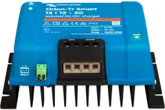 Orion-Tr SmartDC-DC charger or converter 12/24/48 V up to about 400 W, in isolated and non-isolated versions; can be connected in parallel.
 SmartSolar MPPT 100/30 and 100/5030 and 50 A controllers for up to 100 V from panels — at 12 V for about 440 and 700 W of panels.
 Smart BatteryProtectDisconnects DC loads before the battery is discharged; in Li-ion mode controlled by the BMS.
 SmartShuntBattery monitor with 300–2000 A shunt, read on your phone or on a GX device.
 Lynx DistributorModular 1000 A DC busbars: fused distribution with MEGA fuses and monitoring, battery connection, Class-T fuses.
 Cerbo GXSystem control centre and gateway to the VRM portal.
 GX Touch 50/70Optional 5- or 7-inch display for Cerbo GX: system overview, settings, surface or flush mounting.
 Digital Multi ControlWall panel for MultiPlus and Quattro: switch, shore or generator current-limit knob, LEDs and error codes.
What next
- Orion-Tr Smart not charging — step-by-step diagnosissupport
- BMS has cut off charging or dischargingsupport
- Smart BatteryProtect is cutting off loadssupport
- Campervan and van — 12 V installation with a MultiPlus and SuperPack NGdiagram
- Energy balance calculator — how much energy do you need during a working daytool
Manufacturer documentation
- Manual & Drawing BJE-300D — VE.Bus BMS V2, MultiPlus-II 3 kVA, 400 Ah, SmartShunt, Smart BatteryProtect 100 A, MPPT 100/50, 2 × Orion-Tr Smart (12 V/120 V/60 Hz version) — DC side, fuses, controlvictronenergy.com · PDF · EN
- Drawing BJE-256B — VE.Bus BMS with MultiPlus 3 kW 12 V 230 V in a vehicle with alternator — 230 V distribution boardsvictronenergy.com · PDF · EN
- MultiPlus-II 230V — manual: DC cables and fuses, AC wiring, earthing in a mobile installation, 12/3000/120-32 datavictronenergy.com · PDF · EN
- VE.Bus BMS V2 — datasheet: control, outputs, compatibilityvictronenergy.com · PDF · EN
- VE.Bus BMS V2 — manualvictronenergy.com · EN
- Automotive system booklet (rev 03) — advanced lithium system and other vehicle systemsvictronenergy.com · PDF · EN
Content checked against Victron Energy documentation (datasheets and manuals) — as of 22 September 2026. Report a content error · Revision log