

Solar power and electricity in a campervan
From the energy balance to a complete diagram: how much power you really use, how many panels fit on the roof, what battery can support it, how to charge on the road and at campsites, and which cables and fuses are needed. The layout is based on Victron’s official BJE-332 drawing (12 V / 230 V / 50 Hz).
Four decisions in the correct order
A campervan installation is almost always started the wrong way: panels are bought first, then the battery, and only at the end do you discover that the cables are too thin and the inverter has no source of power. The order that saves money is the opposite.
- 1. Calculate consumption. Fridge, pump, lights, laptop charging — in watt-hours per day. This is the only number from which everything else follows.
- 2. Choose the battery. Enough to last two–three days without charging, with a margin for depth of discharge.
- 3. Plan charging. Panels when parked, alternator on the road, shore power at longer stops. You usually need all three.
- 4. Only now 230 V. The inverter is selected for the loads, not as a reserve — every 100 W of continuous power means extra current from the battery.
This guide takes you through all four steps and ends with a diagram that you can transfer to your own vehicle. The figures come from Victron Energy documentation — the BJE-332 installation drawing and the “Wiring Unlimited” wiring manual.

Panels
They lie flat on the roof, so surface area matters, not the rated watts. In Poland, 400 Wp produces about 1.8 kWh per day in June and about 0.14 kWh in December.
Battery
LiFePO₄ delivers practically all of its capacity and lasts 2,500 cycles at 80% depth of discharge — but it must not be charged below freezing.
Alternator
One hour of driving with a 50 A DC-DC charger is about 600 Wh — usually more than a whole day of panel output in winter.
Campsite
A 16 A hookup and a 120 A MultiPlus charger replenish a 300 Ah bank in about three hours.
How it is connected
The layout from Victron’s official BJE-332 drawing: MultiPlus 3 kVA, 300 Ah bank from SuperPack NG batteries, MPPT 100/50 controller, Orion XS DC-DC charger and SmartShunt. Hover over or tap a diagram element — we’ll show you what it is for. The diagram is illustrative; check the original drawing for wiring details.
- Three charging sourcesPanels via MPPT 100/50, alternator via Orion XS, campsite via the MultiPlus charger. They can run at the same time.
- Each source has its own fuseOn the Victron diagram: 60 A for the MPPT, 60 A for the Orion XS, 400 A for the MultiPlus and 100 A for the 12 V load board — all on a common positive busbar.
- Battery protected separatelyEach lithium battery has its own Class T 150 A fuse on the positive terminal; a main switch sits between the busbar and the bank.
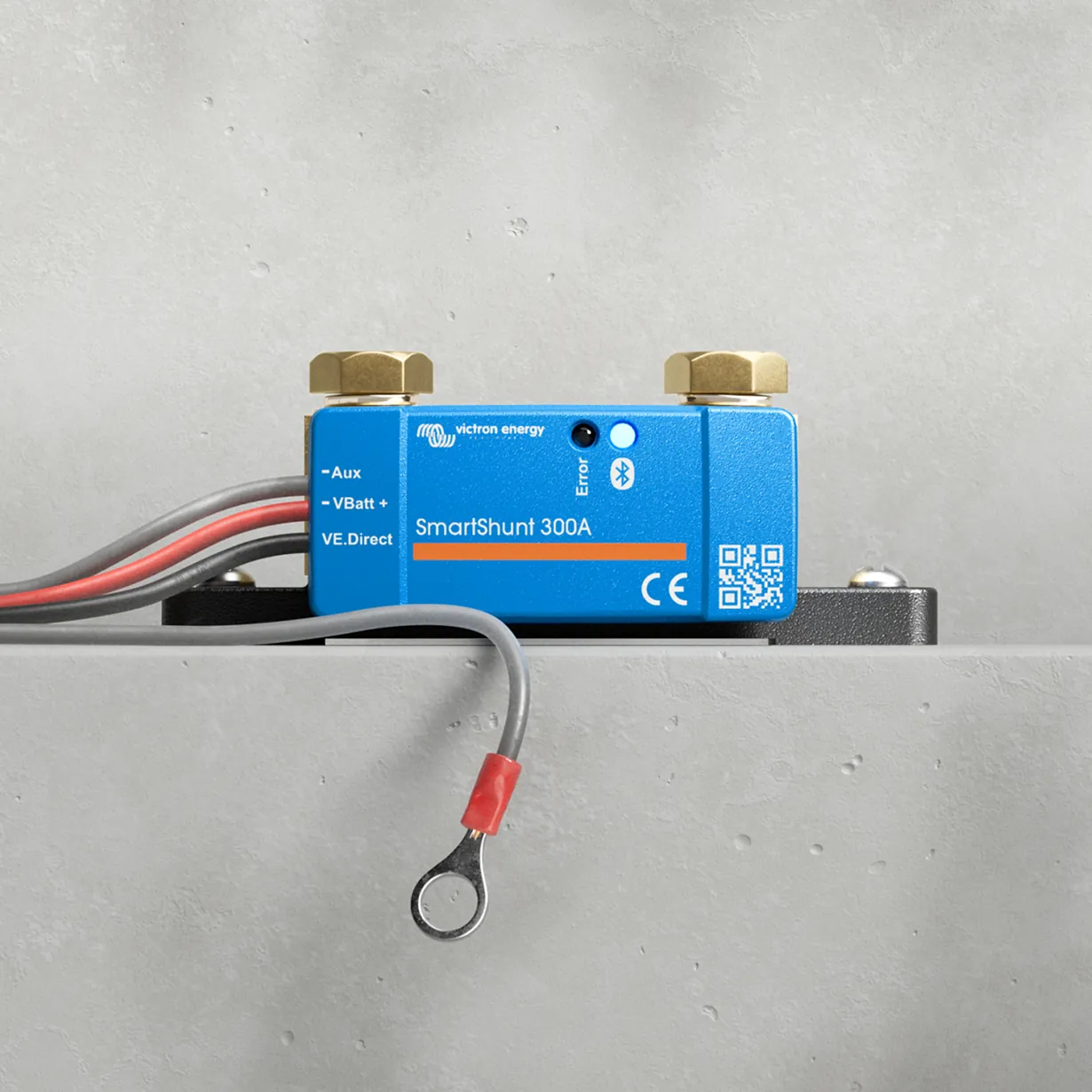
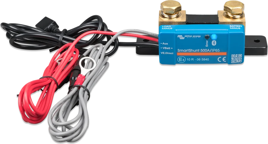
- Measurement in the negativeSmartShunt is in the negative cable, between the bank and the central negative busbar — only there does it see the full current of the installation.
- 230 V after the inverterAC-out-1 works at all times, AC-out-2 only when external power is available. Both outputs require an RCD.
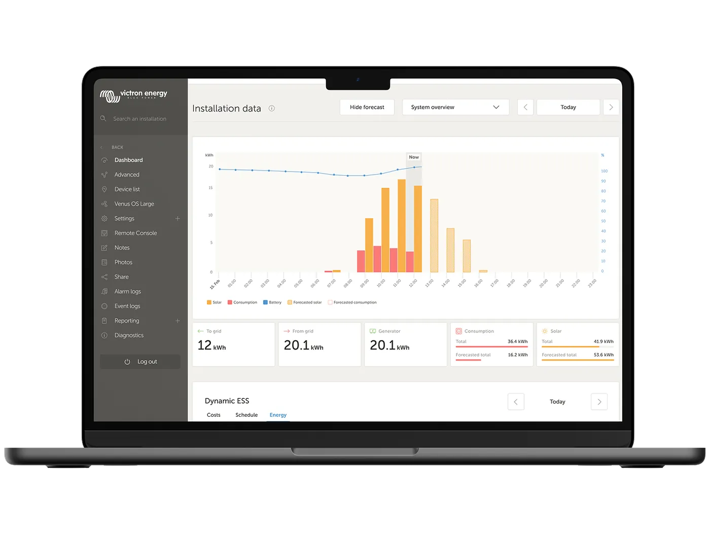
- Everything visible in one placeCerbo GX collects data from the MultiPlus, MPPT, Orion and SmartShunt — on the screen and in the VRM portal.
What exactly the Victron drawing specifies
| Location | According to drawing BJE-332 |
|---|---|
| DC cables to the MultiPlus 3 kVA 12 V | Battery–MultiPlus distance 0–5 m: 4 × 50 mm²; 5–10 m: 4 × 70 mm². In enclosed conduits, the cross-section should be doubled. A single 95 mm² cable only when the total length of positive and negative does not exceed 4 m. |
| MultiPlus fuse | 400 A (MEGA) |
| Battery fuses | Class T 150 A on the positive of each of the three batteries |
| MPPT output and Orion XS output | 60 A each on the common positive busbar |
| 12 V load board | 100 A (example value — match it to the load) |
| MultiPlus AC input | Breaker max. 50 A; in practice sized to the source (campsite usually 16 A), input current limit set in the device |
| AC-out-1 output | With PowerAssist, the sum of current from the hookup and from the inverter can reach 50 + 13 = 63 A. RCD required |
| AC-out-2 output | Up to 16 A, voltage only when powered from the AC input |
| Orion XS input | 60 A fuse at the starter battery positive terminal |
| Earthing the MultiPlus housing | To the central negative busbar, using a cable one size smaller than the total cross-section of the device negatives; the drawing also refers here to the current ABYC rules |
| Battery monitor, Cerbo, dongle | Supplied via 1 A fuses |
Victron deliberately does not specify cable sizes for the whole installation — it does not know the cable lengths in your vehicle. Calculate them with the cable and fuse calculator or according to the rules in the Cables and fuses section.
Layout in the vehicle
The same devices in two different places give two different installations: one that works for years, and another that heats cables and loses voltage. Below are the eight points that matter most.

- 1
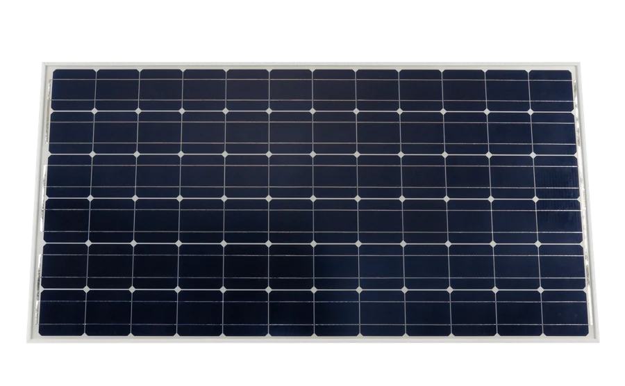 Panels on the roofTwo 200 W modules on a roof rail or on frames bonded to the roof, with a sealed cable gland. Plan them together with the roof hatch and air conditioning — shade from one panel cuts the output of the whole string.
 - 2
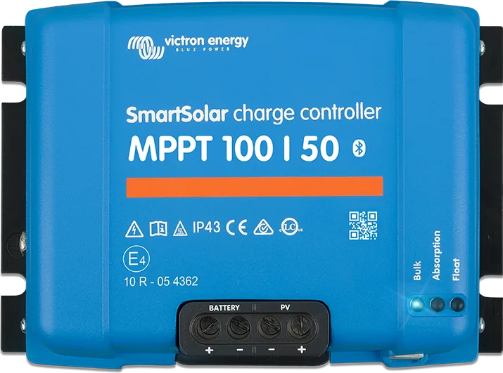 SmartSolar MPPT 100/50In a cupboard right next to the battery, not by the panels. The run from the panels may be long and thin; the run to the battery should be short and thick — that is where the full 50 A flows.
 - 3
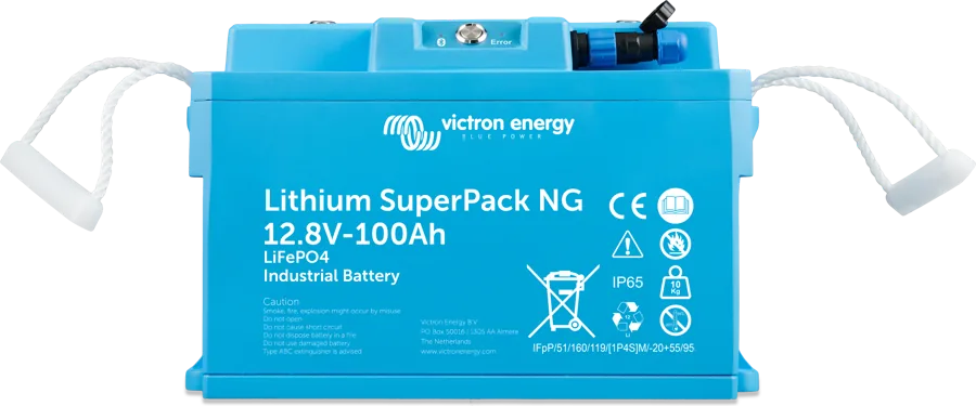 Bank of 3 × SuperPack NGLow down and close to the vehicle centreline — this is the heaviest part of the installation. A lithium battery without a heater must be installed in a heated part of the body: below +5 °C it will not accept charging. A SuperPack NG with heater works down to −30 °C.
 - 4
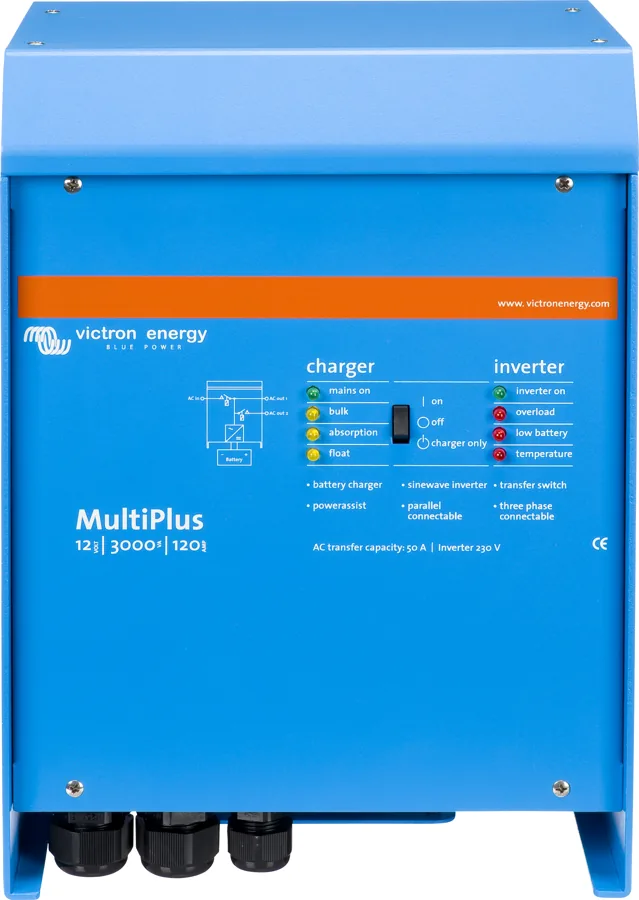 MultiPlus 12/3000/120Inverter/charger above the battery bank, never directly above the batteries. Leave at least 10 cm of free space around the enclosure — the manufacturer forbids a sealed installation.
 - 5
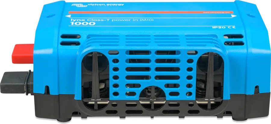 DC busbar and fusesKeep all fuses and the main switch in one accessible place — ideally in a cabinet by the door. Label the circuits, because after a year nobody remembers what is what.
 - 6
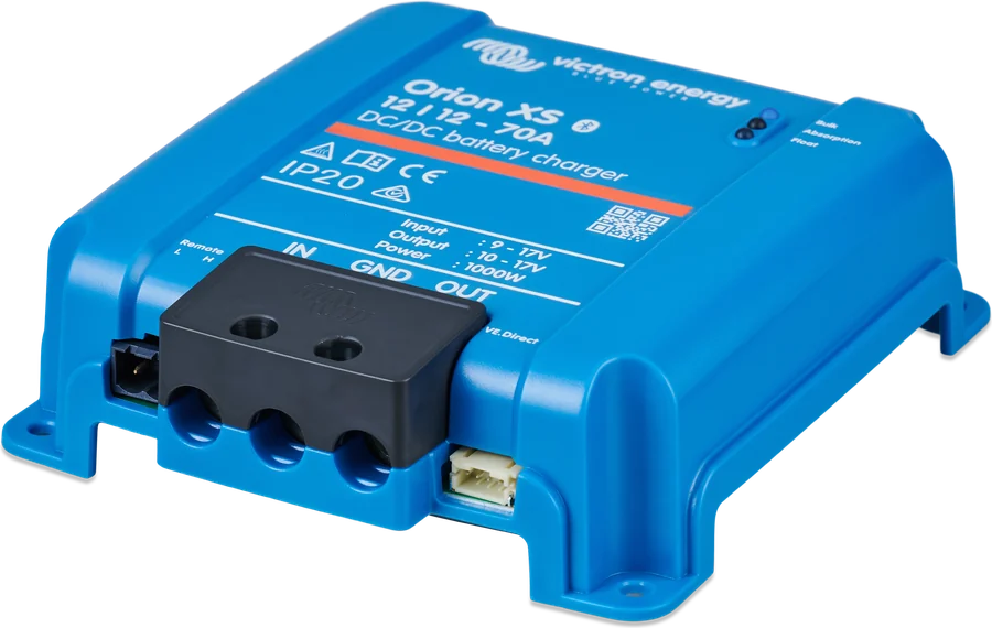 Orion XS 12/12-50Close to the starter battery, for example under the cab seat. The cable from the alternator must have a fuse right by the starter battery.
 - 7
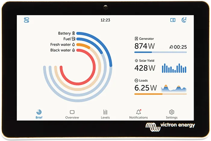 GX control panelGX display or Digital Multi Control by the entrance — from here you set the campsite current limit and check the battery state without reaching for your phone.
 - 8
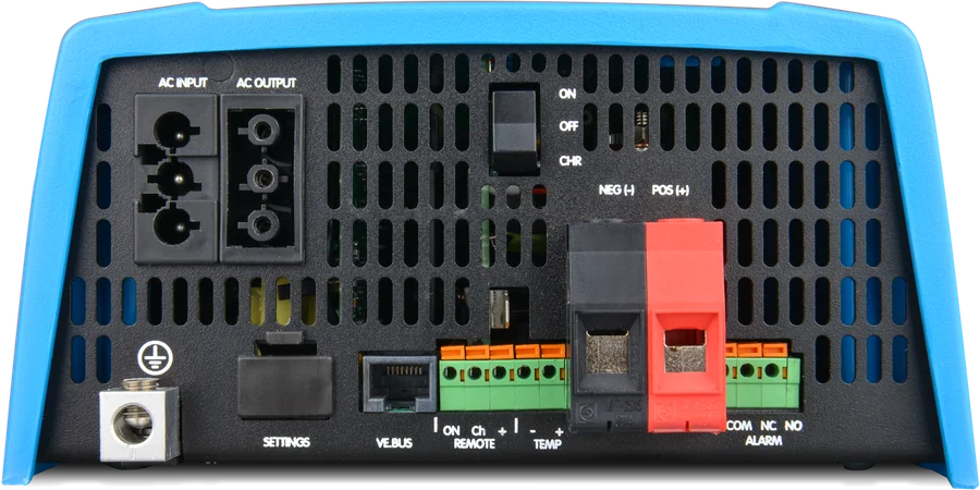 230 V external socketCampsite hook-up on the door side, then the switch and RCD, and then the inverter AC input. The power cable must not run under the wheels or lie in water.
How much energy you really use
The balance is calculated in watt-hours per day: appliance power multiplied by the number of operating hours. A compressor fridge does not run continuously — what matters is its actual run time, in summer even twice as long as in spring.
To convert watt-hours into battery capacity in amp-hours, divide by the system voltage: 1000 Wh at 12 V is about 83 Ah. On top of that come losses: the inverter delivers about 90% of the energy, and a lithium battery has about 92% charge and discharge efficiency.
- Allow for the worst month, the one you actually travel in — not July if you also go away in October.
- Allow for standby consumption: the inverter, battery monitor and GX device draw power all day, even when you are not doing anything.
- Reserve: assume the battery bank delivers 80% of its capacity — that is also how our calculator for LiFePO₄ Smart batteries works.
Example daily balance for a two-person campervan
| Load | Power | Operating time | Energy per day |
|---|---|---|---|
| 12 V compressor fridge | 45 W | 8 h compressor run time | 360 Wh |
| LED lighting | 15 W | 4 h | 60 Wh |
| Water pump | 60 W | 0.5 h | 30 Wh |
| Parking heater (blower) | 25 W | 6 h | 150 Wh |
| Laptop and phones through the inverter | 90 W | 3 h | 270 Wh + inverter losses |
| Electronics standby | approx. 10 W | 24 h | 240 Wh |
| Total | approx. 1.1 kWh (≈ 92 Ah at 12 V) | ||
This is an example, not a standard — take the power values from the nameplates of your own devices. At this consumption, a 300 Ah battery bank lasts for about two and a half days without any charging, using 80% of its capacity.
Roof panels — how much power they will produce
Panels in a campervan lie flat, without an optimal tilt. That changes everything: in summer you lose little, but in winter the yield drops by several times. Below are the data for Warsaw from the PVGIS database (European Commission), converted to a 400 Wp area lying flat — the same figures used by our balance calculator.
That is why in a campervan panels are treated as a source that can cover the whole consumption in season, and outside the season only keep the battery topped up. The alternator and campsite hook-up make up the rest.
| Month | Yield from 1 kWp flat (Warsaw) | 400 Wp array per day | What it means with 1.1 kWh consumption |
|---|---|---|---|
| June | 4.56 kWh | approx. 1.82 kWh | surplus — the battery charges to full |
| April | 3.42 kWh | approx. 1.37 kWh | consumption covered |
| September | 2.66 kWh | approx. 1.06 kWh | just enough, in sunshine |
| October | 1.45 kWh | approx. 0.58 kWh | half the requirement — you need to add more |
| December | 0.36 kWh | approx. 0.14 kWh | the panels only keep the battery topped up |
PVGIS 5.3 data (SARAH3 database, 2005–2023) already include 14% system losses. In the energy balance calculator you will find the same figures for 16 cities.
Series or parallel
Series wiring increases the voltage and thinner cables are enough; parallel wiring increases the current, but shading on one panel hurts less. In series, you must stay within the voltage limit (for the MPPT 100/50 this is 100 V); in parallel, within the array short-circuit current limit: 35 A for the 100/30 and 60 A for the 100/50. A higher short-circuit current can damage the controller.
Frost raises the voltage
The panel open-circuit voltage rises when it is cold. When sizing a string, calculate Voc at the lowest expected temperature, not at 25 °C from the nameplate.
Shade is not a minor issue
A roof light, air conditioner, roof rack or a branch above the pitch can cut the yield of the whole string. With a roof full of obstacles, two smaller strings or two controllers work better.
Solar cable
Victron specifies 4 or 6 mm² solar cables with MC4 connectors — UV-resistant, with tinned conductors. The roof gland must be sealed, and the cables secured so they do not move while driving.
There is always a charge controller between the PV array and the battery. Connecting a panel directly to a battery will damage the battery — “Wiring Unlimited” states this explicitly.
Depending on regulations, a fuse, switch or isolator may be required between the array and the controller. In a campervan it is still worth having one — it lets you safely disconnect the panels for servicing.
MPPT controller — which one and why not PWM
A PWM controller connects the panel to the battery through a switch, so the panel operates at battery voltage. An MPPT controller has a converter: it searches for the panel’s maximum power point and converts excess voltage into current. In a campervan, where roof space is limited, the difference translates directly into how much energy reaches the battery.
The controller name tells you what you may connect to it: 100/50 means 100 V maximum panel voltage and 50 A charging current. With a 12 V system that is up to 700 W; the smaller 100/30 model handles 440 W. Victron controllers have efficiency of up to 98%.
- Set the battery type. For LiFePO₄ you choose the Li-Ion profile and a 12 V system voltage — without this the controller charges according to the lead-acid curve.
- Link it with the rest of the system. The VE.Direct port connects to Cerbo GX, so yield and charging status are shown together with the rest of the installation.
- Mount it close to the battery. The section from the panels can be long and thin; the section to the battery should be short and thick — that is where the full 50 A flows.
MPPT 100/50
Up to 700 W at 12 V — the model shown in Victron’s drawing. Leaves room for adding a third panel.
100 V · 50 AMPPT 150/…
When the array exceeds 700 W or the string has a higher voltage — higher panel voltage limit.
150 V and aboveBattery: lithium or lead-acid
In a campervan the battery works cyclically: you discharge it every day and charge it every day. Under those conditions, the difference between lead-acid and lithium is greatest — not in the price per amp-hour, but in the number of cycles and how much capacity you can actually use.
The LiFePO₄ Smart lithium battery lasts 2500 cycles at 80% discharge, has charging and discharging efficiency of about 92%, and does not lose capacity at high current. The AGM battery at 80% discharge lasts 400 cycles, and at inverter current it delivers clearly less than the figure printed on the case would suggest.
| Feature | LiFePO₄ Smart | Lithium SuperPack NG | AGM Deep Cycle |
|---|---|---|---|
| Cycles at 80% discharge | 2500 | 2500 | 400 |
| Charge and discharge efficiency | 92% | 93% | lower, current-dependent |
| Discharge current | up to 1 C without loss of capacity | at a 5-hour discharge, 85% remains | |
| Charge temperature | from +5 °C to +50 °C | from −30 °C to +60 °C — below 0 °C charging waits until the heater warms the cells | no limit, but capacity drops |
| Discharge temperature | from −20 °C to +50 °C | from −30 °C to +60 °C | no limit |
| Weight for the same usable energy | noticeably lower | higher | |
| Fuse | Class T — lithium gives very high short-circuit currents | MEGA is usually enough | |
Standard Smart LiFePO₄ batteries may only be charged below +5 °C — in an unheated box in winter they will simply stop charging. The SuperPack NG in Victron’s drawing has a built-in heater: at a negative temperature it pauses charging, heats the cells and resumes automatically, with an operating range from −30 °C to +60 °C. If the bank is to sit under the floor, choose a battery with a heater or a heated box.
With a daily use of 1.1 kWh, a 300 Ah bank (3.84 kWh) gives about two and a half days of autonomy, assuming 80% usable capacity. A 200 Ah bank gives just under two days.
Alternator via DC-DC charger
A lithium battery will take as much current as you give it — and a standard alternator is not built for that job. Without a current limiter, it can run at maximum for as long as it takes to overheat. The second problem is voltage: the alternator charges according to a lead-acid curve, so lithium never reaches full charge.
A DC-DC charger solves both: it limits the current drawn from the alternator and charges the bank with its own charge curve. Orion XS 12/12-50 delivers up to 50 A, has efficiency of up to 98.5% and draws under 1.5 mA in standby. One hour of driving at this current is about 600 Wh — more than an entire December day from solar panels.
- Fuse at the starter battery. In Victron’s drawing this is 60 A on the positive terminal of the starter battery, right by the terminal.
- Common negative. The engine negative, starter battery negative and charger output all return to the central negative busbar — without this, starter battery voltage sensing will not work either.
- Engine running detection. In the drawing, terminals L and H are bridged, so in the settings you must enable automatic start and specify the alternator type and the Li-Ion profile.
- Euro 6 vehicles have alternators controlled by the computer — the voltage can drop while driving. We described how to set this up in Orion XS diagnostics.
Inverter/charger and campsite hook-up
MultiPlus combines three functions: a 230 V inverter, a battery charger and an automatic source transfer switch. When you arrive at a campsite, it switches the loads to mains and starts charging the bank, and when you unplug the cable it switches back to battery operation — without any interruption to the supply.
The model in the drawing, 12/3000/120, provides 2,400 W continuous power, 6,000 W peak power and charges the bank at up to 120 A. The “Wiring Unlimited” manual recommends that in a 12 V installation you should not exceed 3,000 VA of inverter power — above that, the currents become so high that it makes more sense to move to 24 V.
- PowerAssist adds battery power when the hook-up is weak — a 6 amp post will not trip the breaker when the kettle is on.
- Input current limit is set for the specific post: from the Digital Multi Control panel, from the GX screen or from your phone.
- AC-out-2 has voltage only when supplied from outside — that is the place for a boiler or air conditioner that makes no sense on battery power.
The AC installation — hook-up, distribution board, RCDs and earthing — should be installed and checked by a qualified electrician. Victron’s drawing shows a “non-isolated” system, with a common negative and vehicle chassis, built to CE/ABYC rules.
A vehicle has no earth electrode in the ground, so the common potential is provided by interconnected metal parts: chassis, engine, metal pipes and the protective contacts of sockets. When operating from an inverter, the neutral conductor of the output must be connected to chassis, otherwise the RCD will not work.
The most common source of problems
At 12 V, currents are high and every metre of thin cable eats voltage. Victron recommends that voltage drop in the circuit should not exceed 2.5% — for a 12 V installation that is only 0.3 V. Exceeding this means an undercharged battery, poorer inverter performance and hot cables.
A quick rule from the “Wiring Unlimited” manual for DC cables up to 5 metres: cross-section in mm² is current divided by 3 — at 200 A, that gives 66 mm². You can calculate it more precisely from the table below or in the calculator.
- Count the total length of the positive and negative, not the distance from the device to the battery.
- Instead of one very thick cable, you can use two thinner ones with the same total cross-sectional area — 2 × 35 mm² replaces 70 mm².
- Use only flexible cables with fine strands; in damp conditions and on boats — tinned strands. Never use cables intended for AC installations.
Maximum current for typical cables
| Cross-section | up to 5 m total | up to 10 m | up to 15 m | up to 20 m |
|---|---|---|---|---|
| 6 mm² | 18 A | 9 A | 6 A | 5 A |
| 10 mm² | 30 A | 15 A | 10 A | 8 A |
| 16 mm² | 48 A | 24 A | 16 A | 12 A |
| 25 mm² | 75 A | 38 A | 25 A | 19 A |
| 35 mm² | 105 A | 53 A | 35 A | 26 A |
| 50 mm² | 150 A | 75 A | 50 A | 38 A |
| 70 mm² | 210 A | 105 A | 70 A | 53 A |
| 95 mm² | 285 A | 143 A | 95 A | 71 A |
Table from the “Wiring Unlimited” manual: the currents shown correspond to a voltage drop of 0.259 V over the total length of the positive and negative cable, without losses at connections.
Fuses: not all are suitable for lithium
A lithium battery can deliver a much higher short-circuit current than a lead-acid battery. That is why not only the fuse rated current matters, but also its interrupting capacity — the highest short-circuit current it can safely break. Victron requires that in a lithium battery installation at least one fuse in the DC circuit has an interrupting capacity not lower than the expected short-circuit current of the bank.
| Fuse type | Max. DC voltage | Interrupting capacity |
|---|---|---|
| Class T (Eaton Bussmann) | 160 V | 200 kA |
| Class T (other manufacturers) | 125–300 V | 20 kA |
| NH blade fuses | 250 V | 25 kA |
| ANL (Blue Sea) | 80 V | 6000 A |
| AMX(L) (Eaton Bussmann) | 125 V | 3000 A |
| MEGA (Littelfuse) | 70 V | 2500 A |
| MRBF (Blue Sea) | 58 V | 2000 A |
| MEGA (Littelfuse) | 58 V | 1000 A |
Summary from “Wiring Unlimited”. Every load connected to the battery should have its own fuse on the positive cable — regardless of how little current it draws.
The order and details that make a difference
Do not fit the main fuses until you have finished and checked all connections. At each load, connect the negative to the central negative busbar first, and only then connect the positive to its fuse.
Victron’s drawing explicitly requires this for the negative cables: all of them should be as short as possible and the same length. It is worth routing the positives the same way — otherwise the batteries in the bank work unevenly and one ages faster.
Cerbo and dongles are connected after the main switch — when it is switched off, they do not discharge the battery. SmartShunt can remain before it, because it draws less than 1 mA.
- Ventilation: at least 10 cm of free space around the MultiPlus, in a dry and ventilated place — do not enclose it tightly.
- Common negative: the starter battery negative, engine and DC-DC charger output are connected to the central negative busbar.
- Final settings: update the device firmware, set the Li-Ion profile and 12 V voltage in the MPPT and Orion, and enter the bank capacity in the battery monitor.
- Label the circuits. Stickers on fuses and busbars save an hour of searching after the first breakdown on the road.
Three versions from the Victron drawing
| Version | Components | Need a phone? |
|---|---|---|
| Simple (BJE-332A) | BMV-712 Smart battery monitor + Digital Multi Control panel — shore power current limit and on / off / charger only switch | No |
| Smart 1 (BJE-332B) | SmartShunt 500 A + VE.Bus Smart dongle — view and control the MultiPlus in the app | Yes |
| Smart 2 (BJE-332C) | SmartShunt + Cerbo GX with GX Touch 50 display, DMC panel optional; remote view via VRM and tank level sensors | No (but you can) |
What to do before the motorhome stands for several months
- Longer停: switch the MultiPlus to “charger only” mode — the inverter will not discharge the battery. The panels will keep the bank topped up only if the vehicle is parked out of the shade.
- Winter storage: first charge the batteries fully, then switch off the MultiPlus and the main isolator. The battery monitor keeps working.
- Check every 4–6 weeks: check the state of charge and protect the batteries from freezing.
- Instead of a running MultiPlus the manufacturer recommends a small maintenance charger for winter storage, for example Blue Smart IP65 12 V/10 A.

Eight mistakes that cost the most
The same faults keep appearing in successive installations. Most of them can be avoided at the planning stage, without extra cost.
Battery too small, too many panels
A classic case: 600 W on the roof and a 100 Ah battery. At midday the panels deliver as much as the battery can accept, and you waste the rest of the energy. First the bank, then the panels.
Cables to the inverter too thin
At 2400 W and 12 V, more than 200 A flows. The Victron drawing specifies 4 × 50 mm² cables for a MultiPlus 3 kVA at distances up to 5 m — not 25 mm² because “it seems to work”.
Fuse without breaking capacity
With a lithium battery, a standard MEGA fuse rated at 58 V will interrupt 1,000 A, and the bank can deliver many times more. At least one fuse in the circuit must be a Class T type.
Battery without a heater in an unheated compartment
A standard LiFePO₄ battery will accept charging only above +5 °C — a bank under the floor simply stops charging in winter and that is not a fault. Heated models, such as SuperPack NG, work down to −30 °C.
Panel in the shade of the roof hatch
One shaded module in a string reduces the output of the whole string. Plan the roof together with hatches, air conditioning and roof rack.
Alternator without a DC-DC charger
A lithium battery connected directly to the alternator loads it to the limit and still will not charge fully. That is what Orion XS is for.
No RCD on the 230 V output
When running from the inverter, the neutral conductor must be connected to ground, otherwise the residual current device will not operate. AC installation must be done by an electrician.
Judging battery state by voltage
LiFePO₄ voltage is almost flat through most of the range — without a shunt in the negative, you do not know whether you have 70% or 30%.
Most common questions about a motorhome installation
How many panels fit in a motorhome and what will they give?
A typical van roof takes 300–600 Wp. With 400 Wp lying flat in Warsaw, that gives about 1.8 kWh per day in June, 1.06 kWh in September and about 0.14 kWh in December (PVGIS data, including 14% losses). In summer that covers the consumption of a two-person camper, in winter it does not.
Which battery for a motorhome: 100, 200 or 300 Ah?
Start from consumption. At 1.1 kWh per day and using 80% of the capacity, a 300 Ah bank gives about two and a half days without charging, 200 Ah gives just under two days, and 100 Ah gives less than a day.
Can I charge a lithium battery directly from the alternator?
It is not worth it: the alternator would run at maximum and charge with a curve intended for lead-acid, so the bank would never reach full charge. A DC-DC charger is fitted between them, for example the Orion XS 12/12-50.
MPPT 100/30 or 100/50?
With a 12 V installation, the 100/30 model will handle up to 440 W of panels, and the 100/50 up to 700 W. If you plan to add a panel, buy the larger one straight away — the controller is cheaper than a second roof modification.
How thick a cable for a 3 kVA inverter?
The Victron drawing specifies for a MultiPlus 3 kVA 12 V: 4 × 50 mm² at a distance up to 5 m and 4 × 70 mm² at 5–10 m. In enclosed conduits, the cross-section has to be doubled. A quick rule for DC up to 5 m: cross-section in mm² equals current divided by 3.
Does a motorhome need an RCD?
Yes. Both MultiPlus outputs, AC-out-1 and AC-out-2, require their own residual current device. When running from the inverter, neutral must be connected to the vehicle ground, otherwise the RCD has nothing to detect.
Are panels enough in winter?
In December, a 400 Wp array in Poland gives about 0.14 kWh per day — that is maintenance level, not supply. In winter, the energy comes mainly from the alternator while driving and from shore power.
What should I do with the installation during winter storage?
Charge the bank fully, switch the MultiPlus to “charger only” mode or switch it off and isolate it with the main switch. Check the state of charge every 4–6 weeks; the manufacturer also recommends a small maintenance charger instead of a running inverter.
Devices in this setup
 MultiPlusInverter/charger 800 VA–20 kW: PowerAssist, UPS under 20 ms, parallel and three-phase operation.
 Lithium SuperPack NGDrop-in LiFePO4 battery with built-in BMS, heater and IP65 — a simple replacement for a lead-acid battery in a campervan.
 SmartSolar MPPT 100/30 and 100/5030 and 50 A controllers for up to 100 V from panels — at 12 V for about 440 and 700 W of panels.
 Orion XSDC-DC charger 50/70 A from the alternator, including with a smart alternator.
 SmartShuntBattery monitor with 300–2000 A shunt, read on your phone or on a GX device.
 BMV-712 SmartBattery monitor with display, alarm and programmable relay.
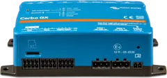 Cerbo GXSystem control centre and gateway to the VRM portal.
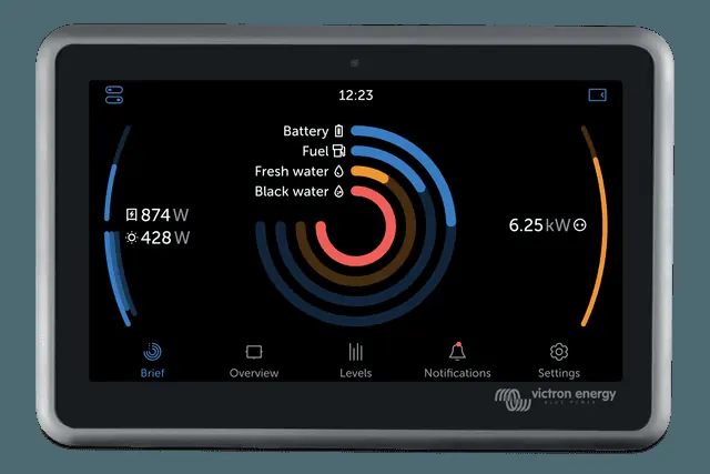
 GX Touch 50/70Optional 5- or 7-inch display for Cerbo GX: system overview, settings, surface or flush mounting.
 Digital Multi ControlWall panel for MultiPlus and Quattro: switch, shore or generator current-limit knob, LEDs and error codes.
What next
Manufacturer documentation
- Van/Motorhome manual & drawing with 3 monitoring setups (BJE-332A/B/C) — layout, fuses, cable sizesvictronenergy.com · PDF · EN
- Wiring Unlimited — voltage drop, cable sizing, fuses, mobile installationsvictronenergy.com · PDF · EN
- PVGIS 5.3 (JRC, European Commission) — solar irradiation data used in the yield tableec.europa.eu
Content compared with Victron Energy documentation (datasheets and manuals) — current as of 20 September 2026. Report a content error · Correction log