
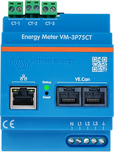
01First check
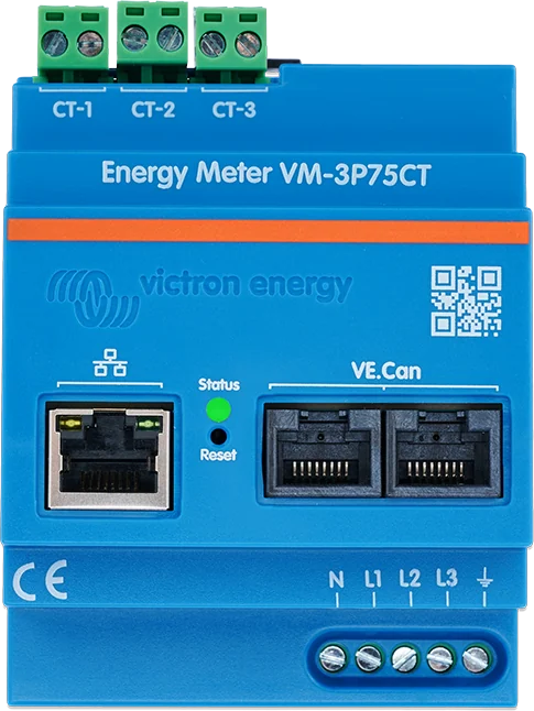
- The meter works straight away as a Grid meter for systems with MultiPlus and Quattro. Configuration in VictronConnect is only needed to change the role and for a manual IP address (instead of DHCP). A firmware update may be needed.
- Power supply — the meter is self-powered from L1–N (85–265 V). It needs a switch or circuit breaker as an isolator (not included). It has a built-in, non-replaceable fuse.
- Indoor use only — operating temperature −10 to 55 °C, IP20 enclosure.
| LED | Meaning | Step |
|---|---|---|
| lights green | all OK, normal operation | — |
| flashes rapidly green-red alternately | bootloader mode — an update is in progress or has failed | 6 |
| lights red | fault — the code is shown in GX, VRM and VictronConnect | 7 |
| short red flashes | energy pulses (each one represents a fixed amount of energy) — not a fault | — |
| flashes green (1 Hz) | device identification, turns off after 60 s | — |
| off | no power supply (the meter is powered from L1–N) | 1 |
Installation and servicing of the meter may only be carried out by a qualified person, with the mains supply isolated. Do not clip the current transformers onto bare conductors. Connecting two phase wires to the N and L1 terminals can damage the meter.
02Step-by-step diagnosis
1Is the meter LED lit?
The meter has no separate power supply — it draws power from the L1 and N terminals (85–265 V AC, 1.45 W consumption). Check the voltage between L1 and N at the meter terminals and the switch that supplies it.
Protection according to the manual: if the meter is connected with cable of the same cross-section as the rest of the circuit after the main breaker, no additional breaker is needed (in most installations in Europe this is 2.5 mm² with a 16 A breaker). With a different cross-section, you need to install a separate breaker in accordance with regulations. The voltage terminals accept 1.0–2.5 mm² conductors.
Go to step 2.
Restore L1–N power. If the voltage is present but the LED does not light, see “When this is a hardware fault”.
2Is the meter visible in the GX device list?
- Via VE.Can — the meter is detected automatically when connected to the VE.Can port and the bus is correctly terminated. The VE.Can network must have terminators at both ends (two are included), and the GX device’s VE.Can port must be set to the 250 kbit/s profile.
- Via Ethernet — connect the meter to the same local network (router) as the GX device (via Ethernet or Wi-Fi). GX recognises it automatically, but you still need to enable it: Settings → Integrations → Modbus Devices → Discovered devices. After first installation and enabling, it is disabled. It is best to leave the IP address on “Automatic (DHCP)”; manual setup is needed very rarely.
- Cables — in both cases, use a good RJ45 network cable, for example Victron RJ45 UTP.
- The Multi RS Solar and Inverter RS Smart manuals recommend avoiding intermediate Wi-Fi links between the meter and GX — they can introduce delays and reduce reliability.
In an ESS system, a missing grid meter causes error #49, and the system may switch to passthrough mode — see “ESS is drawing power from the grid”. Other causes of invisible devices: “GX cannot see the device”.
Go to step 3.
Check the terminators and the VE.Can profile, or enable the meter in the Modbus Devices menu.
3Are the role and phase configuration correct?
In VictronConnect (the gear icon on the Status or Energy page):
- Roles — Grid meter (default), PV inverter, Generator, AC load, EV charger or Heat pump, depending on what you are measuring.
- Position — for the PV inverter, AC load, EV charger and Heat pump roles: whether the meter is on the AC input side or the AC output side of the inverter/charger.
- Phase configuration — “Only L1” for a single-phase installation, “3-phase” (default) for three-phase, “Split phase” for split-phase.
Once the role is set, configuration is complete. You can connect to the meter directly via Ethernet (Modbus/UDP on the local network) or remotely through VictronConnect-Remote when the GX device is connected to VRM.
4Phase readings do not match reality?
- Direction — the transformer has an arrow marked L ← K. It must point towards the loads.
- Correct input and phase — each transformer is marked with the input it belongs to and must clamp around the conductor of the correct phase. The transformers are factory-calibrated together with the inputs — swapping them reduces accuracy.
- Voltage terminals — check that the correct wires have been connected to N, L1, L2 and L3.
- Phase sequence — the Status page in VictronConnect shows the phase sequence in a three-phase configuration; you can enable the wrong-sequence warning with the “Phase rotation” setting (disabled by default).
- Extended transformer leads — they can be extended, but the measurement noise increases slightly. Twist the cores as in the factory cables.
- Installation — the transformers are delicate: open the part marked A in the manual, taking care not to twist the head, and close the head by hand. You can order a damaged transformer from a Victron dealer; it should be replaced by a qualified person.
5Does the current seem too high for the power?
The meter shows the active power of each phase: P = U × I × cos φ (in a three-phase system with the √3 factor). With inductive and capacitive loads the power factor drops, and apparent power (U × I) is greater than active power — this is normal. Check the power factor shown by the meter: a low value confirms that the cause is reactive loads.
- Small electronic devices, such as USB chargers and LED lighting, have a particularly low power factor.
- Generating equipment, such as PV inverters, must by law operate with a power factor close to 1 — this can increase the difference because the loads then account for the ‘weak’ power factor.
- Solutions from the manual: loads with built-in power factor correction (common in modern computer power supplies) or separate power factor compensation devices.
Energy different from the meter reading on the utility meter? Check the “Energy registration method” setting (factory default Vector; arithmetic and absolute are also available). The methods vary by country — confirm it with your energy supplier.
6Does the LED flash green-red alternately?
This is bootloader mode. Either a firmware update is in progress — after it finishes, the meter returns to normal operation by itself (the LED lights green) — or the update failed and the meter is waiting for another attempt. Repeat the update.
- In bootloader mode, you can update the meter only locally with VictronConnect (Ethernet or Wi-Fi on the local network) or remotely from VRM (Remote firmware update, via VE.Can or Ethernet). You cannot do it via VictronConnect-Remote.
- If the update via Ethernet fails, connect the meter to GX via VE.Can, update it, and then switch back to Ethernet.
More about updates: “Firmware update failed”.
7LED lit red — error code?
| Code | Meaning | Action to take |
|---|---|---|
| 116 | calibration data lost | If the meter is not working and the error is active — the meter is faulty; contact the dealer for a replacement. |
| 119 | corrupted settings | The meter cannot read the configuration and has stopped working. Restore factory settings (step 8). |
| 122 | corrupted kWh registers | Reset the kWh counter. |
These codes have a different meaning in the meter — code 122 on Orion XS chargers means something else.
8Restart or factory reset
- Restart without disconnecting the power — briefly press the recessed RESET button. The LED goes off and immediately comes on again.
- Reset with the button — press and hold RESET: the LED goes off for about 3 seconds, the meter starts up and the LED lights green again. Keep holding for about 10 seconds more, until the LED goes off again, then release — the meter will start up.
- Reset in VictronConnect — device list → cogwheel → three dots → “Reset to defaults” → “YES”.
Reset restores: automatic IP address (DHCP), Grid role, three-phase configuration and the “VM-3P75CT” name with the serial number. Then you need to configure the meter again (step 3).
03Not a fault
- Short red flashes — energy pulses. Factory default is one flash per 10 Wh; in the “LED pulse output” setting you can choose 100 Wh, 1 kWh, or turn pulses off.
- Green flashing for 60 seconds — device identification from the app.
- High current with low power — low power factor of the loads (step 5).
- Meter connected via Ethernet does not appear automatically in GX — you need to enable it in the Modbus Devices menu (step 2).
04When it is a hardware fault
According to the manual, active error 116 on a non-working meter means a fault — the meter must be replaced through the dealer. The meter has no user-serviceable parts; do not use it if it is cracked, damaged or not working properly. A damaged current transformer is replaced by a qualified person (you can order the transformer from your Victron dealer). If the LED does not light when voltage is present at terminals L1–N, contact the dealer or installer. Have the firmware version, connection method (VE.Can or Ethernet), role and phase configuration, LED status, error code and photos of the current transformer installation ready.
Devices this applies to
 Energy Meter VM-3P75CTEnergy meter for ESS and AC circuit measurement: 3 x 75 A current transformers included, VE.Can and Ethernet, refresh every 100 ms.
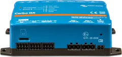 Cerbo GXSystem control centre and gateway to the VRM portal.
 Ekrano GXGX centre with built-in 7″ touchscreen.
Sources
- Energy Meter VM-3P75CT — chapter 7: bootloader, error codes, FAQ (HTML version, status as of 21 September 2026)victronenergy.com · EN
- Energy Meter VM-3P75CT — chapter 4: configuration, enabling in GX, LEDsvictronenergy.com · EN
- Energy Meter VM-3P75CT — chapter 3: current transformers, power supply and protection, VE.Can and Ethernetvictronenergy.com · EN
- Energy Meter VM-3P75CT — chapter 6: restart and factory resetvictronenergy.com · EN
- Energy Meter VM-3P75CT — chapter 5: firmware updatesvictronenergy.com · EN
- Energy Meter VM-3P75CT — chapter 8: technical datavictronenergy.com · EN
- Energy Meter VM-3P75CT — chapter 1: safetyvictronenergy.com · EN
- Multi RS Solar — technical data, note 11: connection to VM-3P75CT without intermediate Wi-Fi linksvictronenergy.com · EN