
Do not install or run the charger directly above the battery or in a sealed compartment with a battery. Batteries emit explosive gases.
01First check
- AC supply — 180–265 VAC range (220–240 VAC nominal) and 45–65 Hz (50–60 Hz nominal). Do not use the charger with a damaged AC cable.
- DC polarity — it must be correct on all connections.
- Error LEDs — on IP22 and IP65, when BULK, ABS, FLOAT and STORAGE flash, it is an error; the code is in VictronConnect. On Smart IP43, an error is indicated by the red ALARM LED, and the status LEDs show the type (step 1).
- In the event of an error, disconnect the AC supply first, then look for the cause.
- Mode — check that it is charging, not power supply mode, Low current or Night.
- Smart IP43: remote connector — charging may be disabled by the remote connector, VictronConnect or a GX device (step 8).
02By symptom
1BULK, ABS, FLOAT and STORAGE LEDs flash
- This is an error indication. You can read the code and description in VictronConnect on a phone or tablet with Bluetooth.
- VictronConnect history covers the last 40 charge cycles, including errors with number and description.
- This is not a fault: on the VE.Smart network (IP22) the status LED briefly goes out every 4 s.
- Power supply mode — BULK, ABS, FLOAT and STORAGE stay on continuously (do not flash). The charging logic is then disabled.
- IP22, Low current mode — the NIGHT LED flashes. Night mode — the NIGHT LED stays on continuously.
- IP65, Low current — the LED for the selected mode flashes (NORMAL / HIGH / LI-ION).
- IP65, Test stage — the TEST LED flashes until the charger determines whether the battery will accept charge (up to 2 min).
- The RECONDITION LED flashes during the recondition stage — this is a stage, not an error code.
- When the MODE button is locked (Lock Mode Button), all LEDs flash when pressed; you cannot change the settings from the button.
Smart IP43 — in the event of a fault, the red ALARM LED lights, and the status LEDs show the type:
| Flashing (ALARM on) | Error |
|---|---|
| BULK | Bulk time protection |
| BULK, ABS and FLOAT | internal error — the same pattern is used for warning #31 (input voltage measurement out of range), but in that case the charger keeps working |
| ABS and STORAGE | charger overvoltage |
| BULK and STORAGE | charger overcurrent |
| LOW | mains voltage too low (step 2) |
| FLOAT and STORAGE | BMS connection lost (step 8) |
No alarm: only the BULK LED flashes — charging is disabled (step 8); BULK and ABS flash (and the RECONDITION LED) — recondition stage. Low current mode is indicated by the LOW LED: the LED table in the IP43 manual says it is on, while the mode description says it flashes.
2No response — AC power
- Mains voltage: nominal 220–240 VAC, permissible range 180–265 VAC. Frequency: nominal 50–60 Hz, range 45–65 Hz.
- Do not start the charger if the AC cable is damaged. Repair: the dealer or installer from whom you bought the unit.
- The AC connection must comply with local regulations. Connect the charger to an earthed socket.
- Smart IP43: supply range 85–250 VAC (full power from 100 VAC, start from 90 VAC), 45–65 Hz; it can also be powered with 90–375 V DC. IEC 320 C14 socket with latch — the mains cable is ordered separately. If the mains voltage is too low, the charger signals an alarm with the LOW LED flashing. After connection to the mains, all LEDs light briefly, then show the charging mode and stage.
3Reverse polarity, short circuit, fuse
- Check the polarity of the DC cable at all connections.
- IP22: with reverse polarity, the user-replaceable fuse blows. Output fuse: 12/15 — 20 A, 12/20 — 30 A, 12/30 — 40 A, 24/8 — 15 A, 24/12 — 20 A, 24/16 — 25 A.
- IP65: with reverse polarity, the charger switches off (there is no description of a replaceable fuse as in IP22). Reverse polarity, short circuit or battery overvoltage causes the battery to be rejected and an error on the LEDs.
- Before disconnecting or connecting to the battery, switch off and isolate the DC system.
- For temporary charging of a battery in a vehicle with negative chassis ground: first connect positive (red insulation) to the positive terminal, then negative (black insulation) to the chassis ground point, not directly to the negative terminal. Disconnect in the reverse order.
- Use a flexible, multi-strand copper DC cable with a sufficient cross-section and fit a fuse close to the battery.
- IP22: tighten the terminal screws to 2.4 Nm.
- Smart IP43: with reverse polarity, the internal fuse blows and cannot be replaced — contact the dealer or installer. With an output short circuit, the charger switches off. Tighten the terminals to 2.4 Nm; fit a fuse or circuit breaker in the DC cable as close to the battery as possible.
- Smart IP43, cable cross-section: the manual gives the minimum cross-sections for each model at up to 3% voltage drop (e.g. 12/50: 16 mm² up to 3 m, beyond that not recommended; 12/30: 10 mm² up to 3 m, 16 mm² up to 4.5 m). Excessive voltage drop can cause charging problems. Stranded cable: individual wire no more than 0.4 mm, flexibility class 5 or 6.
4Battery rejected, Test, deep discharge
- Algorithm: IP22 — 6-stage adaptive (3 stages for Li-ion). IP65 — 7-stage adaptive (4 stages for Li-ion), with a Test stage.
- In IP65, after a short while the TEST LED flashes until the charger determines whether the battery will accept charge (up to 2 min). This is not yet a fault.
- False rejection can happen with a deeply discharged battery with a load connected. Disconnect the loads and try again.
- The Recovery function tries to charge a heavily discharged battery (even down to 0 V) with a low current, then returns to the normal cycle. Low current at the start does not immediately mean a fault.
- When battery UVP has tripped, the charger resets the UVP itself and starts charging.
5Wrong mode, Low, Night, power supply, Li-ion
- Integrated modes: Normal, Normal + Recondition, High, High + Recondition or Li-ion. You select them with the MODE button or in VictronConnect.
- Settings are saved and do not disappear after disconnecting from the mains or the battery.
- 12 V voltages: Normal — 14.4 V absorption, 13.8 V float, 13.2 V storage. High — 14.7 V, 13.8 V, 13.2 V. Li-ion — 14.2 V absorption, float disabled, 13.5 V storage.
- 24 V voltages: Normal — 28.8 V, 27.6 V, 26.4 V. High — 29.4 V, 27.6 V, 26.4 V. Li-ion — 28.4 V absorption, float disabled, 27.0 V storage.
- Do not charge non-rechargeable batteries or Li-ion batteries when the battery temperature is below 0 °C. In Li-ion mode, temperature compensation is disabled.
- Recondition is optional for lead-acid batteries and not recommended for regular use.
- Power supply mode disables the charging logic and supplies a fixed, configurable DC voltage. Do not use it to charge a battery.
- IP22, Low current: current limited to 50% of nominal, fan off, NIGHT LED flashing.
- IP22, Night mode: current limited to 50% of nominal, fan off for 8 h, NIGHT LED on continuously. IP65 has no Night mode.
- IP65, Low current: current limited to a model-dependent level (in the table: Low current 2 A, 3 A, 4 A or 10 A). The NORMAL, HIGH or LI-ION LED flashes.
- Smart IP43: the same Normal, High and Li-ion modes (with optional recondition) and the same voltages for 12 and 24 V; for 36 and 48 V: Normal 43.2/41.4/39.6 V and 57.6/55.2/52.8 V, Li-ion 42.6/40.5 V and 56.8/54 V (absorption/storage). Low current limits the current to 50% of nominal; in VictronConnect you can set your own limit, down to 25%. The manual recommends Low current for small batteries — the charge current should not exceed about 0.3C for lead-acid and about 0.5C for LiFePO4. Power supply mode: BULK, ABS, FLOAT and STORAGE stay on.
6Charges poorly or quickly goes to float/storage
- Do not cover the charger and do not place objects on it. Mount it on a non-combustible surface — the housing gets hot. Good ventilation and free space around it are required.
- IP22: install vertically, terminals down; min. 100 mm clearance above and below. Fan cooling (exception: 12/15 and 24/08). Operating temperature −20 to 50 °C, full power up to 40 °C. Above 40 °C the current is reduced (derating).
- IP65: convection cooling only (no fan). Operating temperature −40 to 50 °C, full power up to 30 °C. Above 30 °C the current is reduced (derating).
- In IP65 the pressure equalisation vent is not a reset button — do not insert sharp or conductive objects into it.
- The FLOAT LED lit continuously = float stage. STORAGE LED = storage stage. This is the normal end of the cycle, not a fault. In Li-ion, float is disabled — after absorption comes storage.
- Adaptive absorption automatically adjusts the absorption time to the battery’s response. A short absorption stage does not automatically mean a fault.
- Also check Low current and Night (step 5) and the history of the last 40 cycles in VictronConnect.
- Smart IP43: convection cooling only (no fan), operating temperature −20 to 60 °C, full current up to 40 °C, then linearly less — down to 25% at 60 °C. Install vertically, terminals down, with at least 100 mm of free space above and below; where airflow is restricted, the manual recommends adding a fan.
- Smart IP43 with multiple outputs: in 1+1 models, the auxiliary output (starter) provides at most 4 A; the total current of all outputs is limited to the rated current. All outputs use one common charging algorithm, so the batteries must be compatible with it (usually the same chemistry).
7VictronConnect, PIN, firmware
- You can identify the error code in VictronConnect (phone or tablet with Bluetooth).
- Default PIN (IP22 manual): on the label on the back of the charger, or 000000 if there is no label.
- PIN reset (IP22 manual): hold MODE for 10 s — the PIN returns to 000000 and pairing is cleared.
- A factory reset does not reset the Bluetooth settings (PIN, pairing).
- Smart IP43: holding MODE for 10 s resets the PIN to 000000 (not to the PIN on the label) — the mode LEDs flash twice. You also re-enable Bluetooth the same way; this also clears pairing, so remove the charger from paired devices.
- IP22 with firmware v3.61 or later has instant readout: voltage, current, stage and alarms are visible without a full Bluetooth connection.
- If the firmware update fails, the app will show the reason — try again. Steps: firmware update. If the app does not connect at all: VictronConnect and Bluetooth.
8Smart IP43: charging disabled (remote, BMS)
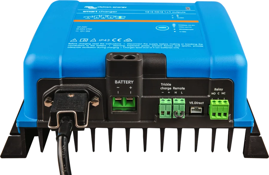
When only the BULK LED flashes (with no alarm), charging is disabled — by the remote connector, the switch in VictronConnect settings, or a GX device.
- Remote connector — factory default is with L and H linked by a bridge. The charger turns on when L and H are shorted (by a switch, relay or, for example, a BMS) or when the voltage on H exceeds 2.9 V (for example, connection to battery positive). It turns off when both contacts are open and ‘floating’ — with no connection to a high or low potential.
- The third option in the manual — L below 3.5 V (for example, connection to battery negative) — is listed among the ways to turn it on, but described in words as “the charger will turn off”. This is an inconsistency in the manual; with this wiring, check the charger’s behaviour.
- Re-enabling charging (remote, VictronConnect, MODE button) starts a new charging cycle.
- The programmable relay works only with AC power and charging enabled — when charging is disabled in any way, the relay also does not work.
- BMS connection lost (FLOAT and STORAGE flash, ALARM lit) — check the BMS connection.
Devices this applies to
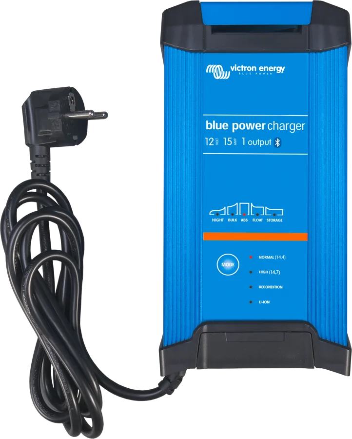
 Blue Smart IP22 Charger230 V charger, 8–30 A, for indoor use, with Bluetooth, night mode and an option for three outputs.
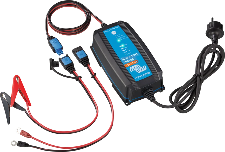
 Blue Smart IP65Mains charger for 12/24 V with Bluetooth and Li-ion mode, IP65 enclosure.
 Smart IP43 ChargerFixed 230 V charger up to 50 A, fanless, with VE.Direct, relay and power supply mode.
What next
The modes, voltages and LEDs are described in the Blue Smart IP22, Blue Smart IP65 and Smart IP43 Charger datasheets. Victron LED meanings: LED decoder. Charger error numbers: MPPT and charger error codes.
Sources
- Blue Smart IP22 Charger manual, Rev. 05 — 08/2025victronenergy.com · EN
- Blue Smart IP65 Charger manual, Rev. 05 — 08/2025victronenergy.com · EN
- Smart IP43 Charger 120-240V — chapter 7: status and error LEDs, VictronConnect (HTML version, as of 22 September 2026)victronenergy.com · EN
- Smart IP43 Charger 120-240V — chapter 5: installation, DC cables, remote, relayvictronenergy.com · EN
- Smart IP43 Charger 120-240V — chapter 4: algorithm, modes, Low current, multiple outputsvictronenergy.com · EN
- Smart IP43 Charger 120-240V — chapter 6: PIN, Bluetooth, resetvictronenergy.com · EN
- Smart IP43 Charger 120-240V — chapter 3: protections (polarity, short circuit, temperature)victronenergy.com · EN
- Smart IP43 Charger 120-240V — chapter 9: technical datavictronenergy.com · EN