
01How to read the codes
- W- (warning) — warning: an issue that will lead to shutdown if nothing is done. A- (alarm) — the cause of a shutdown that has already happened. E- (error) — error.
- Where you will see the code: in the VictronConnect app. The Error LED flashes red — active warning; lights red — active alarm or error. In SuperPack NG, when the LED is lit or flashing, connect to the battery in VictronConnect to see the code; during firmware updates the Bluetooth and Error LEDs flash at the same time.
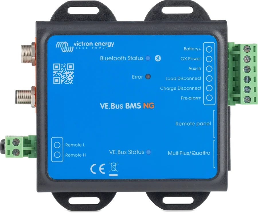
- VE.Bus Status LED (VE.Bus BMS NG): one flash every 10 seconds — the Multi is on and the BMS is sending information frames; off — Multi off (low cell voltage, remote shut-down or panel switch), BMS in low-power mode; fast flashing — the BMS is stuck in bootloader mode, for example after an interrupted update: restart the update in VictronConnect.
- Shutdown without a code: “Allowed to charge: No” in VictronConnect may be caused by battery temperature below 5 °C, battery temperature too high, or reaching the high cell voltage threshold. “Allowed to discharge: No” — discharge floor reached or low cell voltage threshold. In VE.Bus BMS NG, both blocks can also be triggered by the Remote on/off input. During a pre-alarm, the “Allowed to discharge” field shows “Pre-Alarm”.
- SuperPack NG — cause of ATC/ATD shutdown: when ATC or ATD shows “No”, tap the “i” icon next to it to see the reason (#1–#13).
- Lithium NG batteries: the codes are shown by the BMS the battery is connected to. With Lynx Smart BMS NG — see Lynx Smart BMS / NG codes; with smallBMS NG or VE.Bus BMS NG — the codes below.
- Same prefixes, different meaning: for example, W-B05 in smallBMS NG and VE.Bus BMS NG means loss of communication with the battery, but in Lynx Smart BMS it means a BMS cable fault. Always read the code on your device’s page.
The smallBMS NG and VE.Bus BMS NG code tables are identical in both manuals, so we describe them together.
02smallBMS NG and VE.Bus BMS NG
Warning: low cell voltage
Charge the battery or reduce the load to prevent the system from shutting down.
Original: “Low cell voltage” · smallBMS NG · VE.Bus BMS NG
Warning: loss of communication with battery
Check the cables between the BMS and the battery.
Original: “Communication with battery lost” · smallBMS NG · VE.Bus BMS NG
Warning: low SoC
Charge the battery or reduce the load to prevent the system from shutting down.
Original: “Low SoC” · smallBMS NG · VE.Bus BMS NG
Warning: Cellguard firmware cannot be updated
The Cellguard module did not enter bootloader mode and had to be power-cycled. Follow the manufacturer’s recovery document.
Original: “Cellguard firmware cannot be updated” · smallBMS NG · VE.Bus BMS NG
Alarm: low cell voltage
Charge the battery.
Lithium NG battery manual: after a low cell voltage alarm, the voltage of all cells must rise to 3.2 V before the battery clears the alarm.
Self-clearingthe system will enable the loads once the battery has been charged sufficiently.
Original: “Low cell voltage” · smallBMS NG · VE.Bus BMS NG · Lithium NG — troubleshooting
Alarm: loss of communication with battery
Check the cables between the BMS and the battery.
The Lithium NG battery manual lists a loose or damaged BMS cable or connector as a possible cause of a BMS alarm when all cell voltages and temperatures are within limits.
Original: “Communication with battery lost” · smallBMS NG · VE.Bus BMS NG · Lithium NG — troubleshooting
Alarm: low SoC
Charge the battery.
Self-clearingthe system will enable the loads once the battery has been charged sufficiently.
Original: “Low SoC” · smallBMS NG · VE.Bus BMS NG
Alarm: high battery temperature
Battery temperature is too high for charging. Try to lower the ambient temperature.
Original: “High battery temperature” · smallBMS NG · VE.Bus BMS NG
Alarm: low battery temperature
Under Temperature protection has triggered. Raise the battery temperature to resume operation.
Original: “Low battery temperature” · smallBMS NG · VE.Bus BMS NG
Invalid battery configuration
See the “Battery” tab in VictronConnect for details. Check that all battery BMS cables are connected.
Original: “Battery configuration invalid” · smallBMS NG · VE.Bus BMS NG
Invalid battery configuration
See the “Battery” tab in VictronConnect for details. Check that all battery BMS cables are connected.
Original: “Battery configuration invalid” · smallBMS NG · VE.Bus BMS NG
Battery voltage not allowed
Battery voltage is too high or too low. Check the battery voltage and the battery settings in VictronConnect.
The error appears when battery voltage is outside all system voltage ranges — below 9 V or above 60 V.
Original: “Battery voltage not allowed” · smallBMS NG · VE.Bus BMS NG
Hardware fault
Contact the Victron dealer from whom the device was purchased.
Original: “Hardware error” · smallBMS NG · VE.Bus BMS NG
ATC/ATD failure
Check the ATC/ATD wiring (charge and discharge enable signals) and make sure all loads and chargers are controlled by ATC/ATD — if applicable, also via CAN-bus communication.
Original: “ATC/ATD failure” · smallBMS NG · VE.Bus BMS NG
Calibration data lost
The calibration parameters have returned to their default values (the manual adds: “sector check”).
Original: “Calibration lost” · smallBMS NG · VE.Bus BMS NG
Settings data lost
The settings data is corrupted. Go to the settings page and restore the default settings.
Original: “Setting data lost” · smallBMS NG · VE.Bus BMS NG
03Lithium SuperPack NG
Warning: low cell voltage
Charge the battery or reduce the load to prevent the system from shutting down.
When the low voltage cut-off threshold is reached, the BMS disconnects the loads and blocks discharge. If the condition does not clear within 30 seconds, ATD (discharge enable) is disabled and alarm A-B01 appears.
Original: “Low cell voltage” · Victron source · automatic protections
Warning: high current
Reduce the current to prevent the system from switching off — reduce the load or switch off some loads.
Original: “High current” · Victron source
Warning: communication with cell pack lost
Internal communication is not working. Contact the dealer.
Original: “Communication battery lost (cellpack)” · Victron source
Warning: loads will be disconnected
The loads will be switched off if the problem is not resolved — for example due to low battery voltage. This warning always appears together with the reason for the imminent disconnection.
Original: “Load will disconnect” · Victron source
Warning: low SoC
Charge the battery or reduce the load to prevent the system from shutting down.
Original: “Low SoC” · Victron source
Warning: Cellguard firmware cannot be updated
The Cellguard module did not enter bootloader mode and had to be power-cycled. Follow the manufacturer’s recovery document.
Original: “Cellguard Firmware cannot be updated” · Victron source
Alarm: low cell voltage
Charge the battery or reduce the load.
Discharge (ATD) is blocked — the alarm appears when warning W-B01 does not clear within 30 seconds.
Self-clearingwhen the battery returns to the operating range.
Original: “Low cell voltage” · Victron source · automatic protections
Alarm: high current
Reduce the charge current or switch off some loads. The system will try to re-enable the chargers or loads after 5 minutes.
The overcurrent protection operates within 5 seconds after the maximum continuous current is exceeded, and faster when the current exceeds 3C. There is no permanent lockout: the battery switches charging or discharging off and on again in 5-minute cycles until the overload clears.
Self-clearingafter 5 minutes the battery tries again.
Original: “High current” · Victron source · automatic protections
Alarm: high BMS temperature
Check the ambient temperature and whether the cooling fans are working.
Original: “High BMS temperature” · Victron source
Alarm: loads disconnected
The loads were switched off by ATD. Clear the alarm by charging the battery.
Original: “Load disconnected” · Victron source
Alarm: low SoC
Charge the battery.
Self-clearingthe system will enable the loads once the battery has been charged sufficiently.
Original: “Low SoC” · Victron source
Alarm: high battery temperature
Battery temperature is too high. Try to lower the ambient temperature.
Self-clearingwhen the battery temperature returns to the operating range.
Original: “High battery temperature” · Victron source · automatic protections
Alarm: low battery temperature
Battery temperature is too low. Try to raise the ambient temperature.
Self-clearingwhen the battery temperature returns to the operating range.
Original: “Low battery temperature” · Victron source · automatic protections
Hardware fault
Contact the Victron dealer from whom the battery was purchased.
Original: “Hardware error” · Victron source
Pre-charge error
The load resistance is too low to pre-charge the loads. Disconnect or reduce some DC loads.
In the event of a short circuit, the battery makes up to three pre-charge attempts with a 30-second pause. If the short circuit persists and the output voltage does not rise, E-B25 appears and charging and discharging are blocked.
Self-clearingwhen the short circuit is removed (the load voltage falls below the threshold).
Original: “Pre-charge error” · Victron source · automatic protections
Pre-charge timeout
The load capacitance is too large for pre-charge. Disconnect some DC loads.
Discharge is blocked, charging remains allowed. The battery waits 10 minutes and then retries pre-charge (three attempts) — the cycle repeats until the output can be enabled.
Self-clearingthe battery retries pre-charge every 10 minutes.
Original: “Pre-charge timeout” · Victron source · automatic protections
High cell voltage
The manual gives no recommendation for this code.
Original: “High cell voltage” · Victron source
External disconnection signal
The EFS signal has activated — internal critical error (Internal Fatal Error). Disconnect the battery from the loads and chargers immediately. Contact the dealer.
Original: “External disconnection signal” · Victron source
Battery safety lock
What to do: 1) check the cell voltages; 2) once the cause has been removed, switch the battery off and on again.
The lock appears when cell voltage falls below the lock threshold, for example due to self-discharge: discharge is blocked first, and after 30 seconds charging is also blocked.
Do not let this happen: deep discharge can permanently damage the cells and void the warranty. If it has happened, see the procedure after very deep discharge.
Does not clear automaticallyyou need to fully switch the battery off and on again after removing the cause.
Original: “Battery safety lock” · Victron source · automatic protections · procedure
Calibration data lost
Contact the dealer.
Original: “Calibration lost” · Victron source
Settings data lost
Go to the settings page and restore the factory settings. Bluetooth pairing data will also be reset — you need to remove the product from the list of paired devices.
Original: “Settings data lost” · Victron source
04SuperPack NG: reasons for ATC/ATD shutdown
Disabled by the battery
The battery blocks charging or discharging. This can happen when there is no communication with the battery yet, or the battery configuration is incorrect.
Condition in the battery: no communication with the battery, incorrect battery configuration, incorrect battery voltage.
Applies to: ATC and ATD.
Original: “#1: Disabled by battery” · Victron source
High temperature
The temperature is too high. This is part of the battery protections and does not necessarily mean a fault. Check the ambient temperature and whether the fans are working.
Battery condition: FET transistors or cells too hot.
Applies to: ATC and ATD.
Originally: “#3: High temperature” · Victron source
Internal reason
The device is in an alarm state and is blocking normal operation. Check the alarm notifications and устранить their cause.
Battery condition: system error — loss of user settings, loss of calibration data, ATC/ATD failure, or an external disconnect signal.
Applies to: ATC and ATD.
Originally: “#5: Internal reason” · Victron source
Overloaded
The manual gives no description or recommendations — see errors E-B35 and E-B25.
Battery condition: pre-charge time exceeded (ATD only) or pre-charge error.
Applies to: ATC and ATD.
Originally: “#6: Overloaded” · Victron source
Disabled by the user
The battery was switched off remotely in VictronConnect. Check that the On/Off settings are as you want them.
Battery condition: switched off in VictronConnect.
Applies to: ATC and ATD.
Originally: “#8: Disabled by the user” · Victron source
Low temperature
The temperature is too low. This is part of the battery protection and does not necessarily mean a fault.
Battery condition: cell temperature too low.
Applies to: ATC and ATD.
Originally: “#9: Low temperature” · Victron source
High voltage
The voltage of one or more cells is too high.
Battery condition: cell overvoltage.
Applies to: ATC only (charging).
Originally: “#10: High voltage” · Victron source
Low voltage
The voltage of one or more cells is too low.
Battery condition: battery bank or cell voltage too low.
Applies to: ATD only (discharging).
Originally: “#11: Low voltage” · Victron source
High current
The charge or discharge current is too high.
Battery condition: battery current exceeded.
Applies to: ATC and ATD.
Originally: “#12: High current” · Victron source
Low SoC
The manual gives no description — discharge is blocked because the SoC has fallen below the set Discharge floor threshold.
Battery condition: SoC below the Discharge floor threshold.
Applies to: ATD only (discharging).
Originally: “#13: Low SoC” · Victron source
05SuperPack NG: procedure after very deep discharge
If battery voltage falls below 10 V (20 V or 40 V in 24 V and 48 V batteries) or the voltage of any cell falls below 2.5 V, the battery may be permanently damaged — and the warranty voided. The lower the voltage, the more severe the damage is usually. The manual describes a procedure that may allow you to recover the battery, but there is no guarantee of success: permanent cell damage and loss of part of the capacity are possible, even if recovery appears successful.
A supervising person must be present at all times. Perform this only for one battery — in a system with several batteries, disconnect them and repeat the procedure for each one separately. If the battery heats up or swells, stop charging immediately: the battery is irreversibly damaged and must not be used any further.
- Set the charger or power supply to 13.8 V for a 12 V battery, 27.6 V for 24 V, 55.2 V for 48 V.
- Cells below 2.0 V: charge at 0.1 A until the voltage of the lowest cell rises to at least 2.5 V. Keep a close eye on the battery.
- Lowest cell above 2.5 V: current 0.1 C for a 100 Ah battery is 10 A. Record the battery voltage and cell voltages, start charging and record them regularly. The BMS may switch the charger on and off repeatedly — with a large cell imbalance this is normal. If the voltage of any cell does not start to rise within the first 30 minutes, stop: the battery cannot be recovered. Check the temperature regularly — if it rises sharply, stop charging.
- Once you reach 13.8 V (27.6 V or 55.2 V), raise the charging voltage to 14.2 V (28.4 V or 56.8 V) and the current to 0.5 C — for 100 Ah this is 50 A. Cell voltages will now rise more slowly; this is normal. Leave the charger connected for 6 hours.
- Check the cell voltages they should differ by no more than 0.1 V. A larger difference in one or more cells means the battery is damaged.
- Disconnect the charger and wait several hours the battery voltage should stabilise well above 12.8 V (25.6 V or 51.2 V), usually around 13.2 V (26.4 V or 52.8 V) or higher, and the cell voltages should still be within 0.1 V.
- After 24 hours measure again if the voltage has fallen below 12.8 V (25.6 V or 51.2 V) or there is a clear cell imbalance, the battery is damaged beyond recovery.
Source: Lithium SuperPack NG manual, section 6.2.1.
Devices this applies to
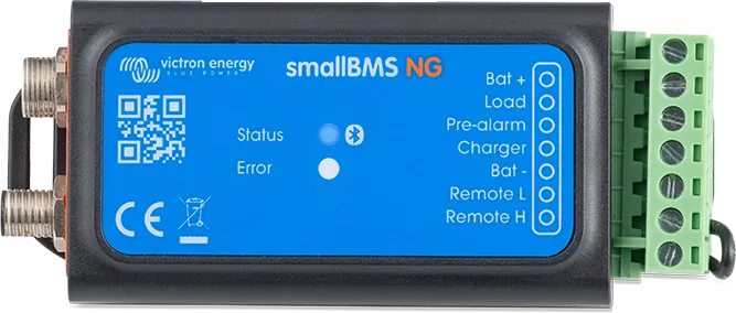
 smallBMS NGSimple BMS for Lithium NG batteries without VE.Bus — controls chargers and loads via outputs, with Bluetooth.
 VE.Bus BMS NGBMS for Lithium NG batteries in a system with MultiPlus or Quattro — Bluetooth, SoC on GX, discharge floor.
 Lithium SuperPack NGDrop-in LiFePO4 battery with built-in BMS, heater and IP65 — a simple replacement for a lead-acid battery in a campervan.
 Lithium NGVictron’s new generation of LiFePO4 batteries: 12.8/25.6/51.2 V, IP65, built-in current measurement — only with BMS NG.
What next
BMS cut off charging? Go through the diagnostics for “BMS cut off charging”. Deeply discharged lithium battery — “Lithium battery discharged”. Charging in frost — “LiFePO4 in winter”. Lynx Smart BMS and Lynx Smart BMS NG codes — separate page. If the manufacturer indicates a hardware fault, contact the dealer or installer from whom you bought the device.
Sources
- smallBMS NG manual — section 5.2: LEDs, warnings, alarms and errors (HTML version, as of 21 September 2026)victronenergy.com · EN
- VE.Bus BMS NG manual — section 5.3: LEDs, warnings, alarms and errors (HTML version, as of 21 September 2026)victronenergy.com · EN
- Lithium SuperPack NG manual — section 6: codes, automatic protections, recovery procedure, ATC/ATD causes (HTML version, as of 21 September 2026)victronenergy.com · EN
- Lithium NG 12.8 V battery manual — sections 6.2.4 and 7: BMS alarmsvictronenergy.com · EN