
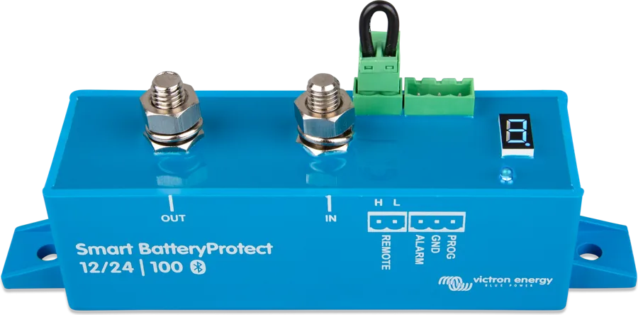
01First check
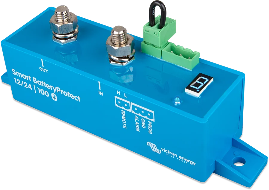
- Current direction — the SBP only conducts current from IN (battery) to OUT (loads). Current in the opposite direction is prohibited and damages the device (step 8).
- Code on the display or in VictronConnect — the SBP shows errors E0–E8 and warnings P2, P3. After 5 minutes, the code disappears from the display to reduce power consumption — a blank display does not therefore mean there was no error. Check it in the app; key values and warnings are also visible without connecting, via Instant Readout.
- Dot on the display — lit continuously: the SBP is trying to switch the output on; flashes every 5 s: output is on; flashes every 2 s in Li-ion mode: output is “in the process of switching on” (step 4).
| Code | Meaning | Step |
|---|---|---|
| P3 / E3 | low voltage — warning / disconnect after 90 s | 3 |
| E7 | BMS lockout (Li-ion mode) | 4 |
| E1 | short circuit, overload or excessive starting current | 5 |
| P2 / E2 | overtemperature — warning / disconnect | 6 |
| E4 | overvoltage | 7 |
| E8 | reverse current (from OUT to IN) | 8 |
| E0, E5, E6 | internal errors | fault |
Full code descriptions: Smart BatteryProtect error codes.
The manual does not allow an inverter or inverter/charger to be connected to the SBP through its DC input under any circumstances — reverse current may flow and damage the SBP. The SBP should control such a device through its remote port. The cable between the battery and the SBP must have a fuse sized according to local regulations.
02Step-by-step diagnosis
1Does the SBP have power and a proper ground?
- The battery positive must be connected to the IN terminal — through a fuse.
- The SBP needs a separate ground wire: the supplied 1.5 mm² cable from the GND terminal straight to the battery negative (or vehicle chassis). Do not connect any other equipment to it. The GND wire must be protected — a 300 mA fuse is sufficient.
- Operating voltage range: 6–35 V (12/24 V version) or 24–70 V (48 V version).
- Mount the SBP in a well-ventilated place, preferably close to the battery (up to 50 cm), but not above it — because of possible corrosive gases.
Go to step 2.
Correct the IN supply and GND wire, check both fuses.
2Is the remote connector closed?
From the factory, the L and H pins on the remote connector are linked by a bridge. Removing it immediately disconnects the loads. You can use a switch instead of the bridge:
- between H and L,
- between battery positive and H pin (H in high state — loads on),
- between battery negative and L pin.
The SBP switches the loads on 1 second after the remote circuit is closed and disconnects them immediately when it is opened (in Li-ion mode, a further 30-second delay also applies — step 4). Programming by the PROG–GND method requires the bridge to be removed from the remote connector — after programming, check that it has been put back.
Go to step 3.
Fit the bridge or repair the connection to the switch or BMS.
3Disconnects at low voltage (P3, E3) or will not switch on after charging?
When the voltage falls below the switch-off threshold, the alarm output is activated after 12 seconds (buzzer, LED or relay), and after 90 seconds the SBP disconnects the loads — it then shows E3. Starting the engine does not therefore trigger an alarm. A quick response during this time — reducing the load or starting charging — can prevent disconnection. The loads return when the voltage rises above the restart threshold — with a 30-second delay.
- Will not switch on after charging — compare the battery voltage with the set restart threshold. In some settings it is high (for example 13.8 V in setting 4 for 12 V).
- Disconnects even though the battery is charged — check the cable between battery positive and the SBP. According to the manual, voltage drop on a long or too-thin cable can trigger a short-circuit alarm when a load starts or an unexpected shutdown.
- E3 repeats — the manual instructs you to switch off or disconnect the loads, charge the battery and check whether the charging system and battery are functioning correctly.
You set the thresholds in VictronConnect (including custom ones) or by the PROG–GND method: the display cycles through settings 0–9, and releasing the button selects the setting. The factory values (10.5 V and 12 V for 12 V, 42 V and 48 V for 48 V) correspond to setting 0.
| Setting | 12 V: switch-off / restart | 24 V: switch-off / restart | 48 V: switch-off / restart |
|---|---|---|---|
| 0 | 10.5 / 12.0 V | 21.0 / 24.0 V | 42.0 / 48.0 V |
| 1 | 10.0 / 11.5 V | 20.0 / 23.0 V | 40.0 / 46.0 V |
| 2 | 9.5 / 11.5 V | 19.0 / 23.0 V | 38.0 / 46.0 V |
| 3 | 11.25 / 13.25 V | 22.5 / 26.5 V | 45.0 / 53.0 V |
| 4 | 11.5 / 13.8 V | 23.0 / 27.6 V | 46.0 / 55.2 V |
| 5 | 10.5 / 12.8 V | 21.0 / 25.6 V | 42.0 / 51.2 V |
| 6 | 11.5 / 12.8 V | 23.0 / 25.6 V | 46.0 / 51.2 V |
| 7 | 11.8 / 12.8 V | 23.6 / 25.6 V | 47.2 / 51.2 V |
| 8 | 12.0 / 13.0 V | 24.0 / 26.0 V | 48.0 / 52.0 V |
| 9 | 10.0 / 13.2 V | 20.0 / 26.4 V | 40.0 / 52.8 V |
In Li-ion mode (C), the voltage thresholds and alarm output are inactive — the loads are disconnected by the signal from the BMS instead (step 4).
4Lithium battery with BMS — Li-ion mode, E7?
Choose Li-ion mode (C) only when the BMS has a load disconnect or charge disconnect output. Batteries with a built-in BMS (so-called drop-in) usually do not have it — for those, the manual says to set mode A or B. In Li-ion mode, the SBP voltage thresholds do not operate.
- Connection — the BMS load disconnect (or charge disconnect) output is connected to the H pin of the remote connector. A potential-free contact, for example ATD in Lynx Smart BMS, is connected between L and H.
- Disconnection — when the BMS output changes from high to “floating” (or the ATD contact opens), the SBP immediately disconnects the loads.
- 30-second delay — after disconnection, the SBP will not switch on for 30 seconds, even if it receives permission during that time; afterwards it responds immediately. In Li-ion mode, a dot flashing every 2 seconds means the output is in the process of switching on.
- E7 — if the BMS disconnects and reconnects the SBP three times in a row (typical when switching off due to low cell voltage, especially when no other loads are connected to the battery), the SBP is switched off. It will switch on when the voltage has been above 13 V (12 V system), 26 V (24 V) or 52 V (48 V) for at least 30 seconds — this indicates that the battery is charging. Check the BMS codes and history, charge the battery, and check the wiring between the BMS and the SBP remote connector.
In the 48 V version manual, the E7 description in the appendix gives thresholds of 13 V and 26 V (as for 12/24 V), while sections 3 and 4 of the same manual give 52 V. Has the BMS also disconnected charging? See “BMS disconnected charging”.
5Disconnects when a load is switched on (E1)?
E1 indicates the short-circuit protection has tripped — due to a short circuit, overload, or excessive inrush current. SBP tries to switch the loads on every 5 seconds; after two attempts it shows E1. The most common case in the manual: an inverter or inverter/charger connected directly to the SBP output — the capacitors on its DC input trigger the protection. Control such a load via its remote port, not by disconnecting the power cable.
- Check whether there is a short circuit in the load circuit.
- Check whether the load current does not exceed the SBP’s capacity.
- Check for loose connections and cable cross-section — voltage drop on the battery cable can also trigger the short-circuit alarm (step 3).
| Model | Continuous current | Peak current | Terminals, torque |
|---|---|---|---|
| SBP-65 (12/24 V) | 65 A | 250 A | M6, 5 Nm |
| SBP-100 (12/24 V) | 100 A | 600 A | M8, 9 Nm |
| SBP-220 (12/24 V) | 220 A | 600 A | M8, 9 Nm |
| SBP 48 V 100 A | 100 A | 250 A | M8, 9 Nm |
6Overtemperature (P2, E2)?
P2 warns that the internal temperature is close to the limit — the manual requires urgent action before the SBP disconnects the loads (E2). What to check:
- whether the load current does not exceed the SBP’s capacity (table in step 5);
- whether the connections are not loose or high-resistance, and whether the cable cross-section is correct;
- whether the SBP is installed in a hot place or within the reach of heat radiation — move it to a cooler place or add active cooling.
The SBP delivers full current at temperatures from −40 to 40 °C; at 50 °C — up to 60% of the rated current.
7Overvoltage (E4) or system voltage misdetected?
In an overvoltage situation, the SBP disconnects the loads immediately. In the 12/24 V version, the threshold is 16 V (12 V system) and 32 V (24 V) according to sections 4.1 and 7.1, and 16.3 V and 32.6 V according to section 2; in the 48 V version — 64 V. The manual says to check the settings of all chargers (especially the system voltage and charge voltages), the charging system operation, and the system voltage set in the SBP.
The SBP 12/24 V detects the system voltage only once — at first power-up — and stores it. After moving it to another installation, you must detect it again: with position “d” in PROG–GND programming or in VictronConnect, where you can check in the settings whether the detected battery voltage matches the system voltage. If the SBP has stored 12 V in a 24 V installation, its normal voltage exceeds the 16 V overvoltage threshold.
The manual for the 48 V version also refers to position “d”, but this position is not in its programming table.
8Reverse current (E8) or SBP at the charger?
The SBP works in only one direction — current to the load or current from the charger, never both at once, and always from IN to OUT. When the voltage on OUT is higher than on IN, uncontrolled reverse current flows, which can permanently damage the SBP. Therefore never use the SBP to charge one battery from another.
- Check the mounting direction — current must flow from IN to OUT.
- Check whether a charging source is not mistakenly connected to the OUT circuit.
- If the SBP disconnects a charger, the charger positive goes to the IN terminal, and no loads may be connected to the IN circuit. To control a charger and loads at the same time, two separate SBPs are used.
9Can’t see the SBP in VictronConnect or programme it?
- Bluetooth disabled in the app — you can re-enable it only with the PROG–GND method: position “F” enables Bluetooth, “h” disables it.
- Unknown PIN — position “P” resets the PIN; then delete the SBP pairing data from previously paired devices.
- PROG–GND method — battery positive on IN, ground wire on GND, OUT terminal not yet connected, jumper from remote removed. Short PROG to GND (preferably with a button): the display steps through the settings, releasing selects the position, and the SBP confirms it twice. Another short selects the operating mode (A, b, C); the same table also includes special positions (d, F, h, P).
- The manual recommends not connecting the load output until the SBP is fully programmed.
Other connection problems: “VictronConnect does not connect via Bluetooth”.
03Not a fault
- Loads do not switch off immediately after voltage drops — the alarm activates after 12 seconds, disconnection occurs after 90 seconds; a brief drop during engine starting does not switch anything off.
- After voltage returns, the loads switch on after 30 seconds — this is the restart delay.
- In Li-ion mode the SBP waits 30 seconds after a disconnect signal from the BMS, even if permission returns immediately.
- The display does not show the code — after 5 minutes the code disappears from the display; check it in VictronConnect.
- In mode A, during overvoltage the alarm sounds intermittently until the cause is removed, and after it is removed there is no restart delay.
04When it is a hardware fault
According to the manual, E0 (calibration data error) and E6 (reference voltage error) are internal faults you cannot clear yourself — the SBP must be replaced. For E5 (configuration data error), restore factory settings (Settings → More options → Reset to defaults), disconnect all power for 3 minutes, and configure the SBP again; if that does not help, contact the seller. Reverse current can permanently damage the SBP. For a replacement, contact the seller or installer — prepare the model, serial number, error code, operating mode and threshold settings, wiring description (what is on IN, what is on OUT, what is on the remote connector), and load current.
Devices this applies to
 Smart BatteryProtectDisconnects DC loads before the battery is discharged; in Li-ion mode controlled by the BMS.
 Lynx Smart BMS / NGBMS with contactor and current measurement for Smart LiFePO4 or Lithium NG banks.
 smallBMS NGSimple BMS for Lithium NG batteries without VE.Bus — controls chargers and loads via outputs, with Bluetooth.
 VE.Bus BMS V2BMS for Lithium Smart batteries in a system with MultiPlus or Quattro — controls the inverter, chargers and loads.
Sources
- Smart BatteryProtect 12/24V — ch. 4: operating modes, programming, status indicator, remote and short circuit, codes (HTML version, status as of 21 September 2026)victronenergy.com · EN
- Smart BatteryProtect 12/24V — ch. 3: installation, inverters, wiring examples with BMSvictronenergy.com · EN
- Smart BatteryProtect 12/24V — ch. 7: error and warning codesvictronenergy.com · EN
- Smart BatteryProtect 12/24V — ch. 2: featuresvictronenergy.com · EN
- Smart BatteryProtect 12/24V — ch. 6: technical datavictronenergy.com · EN
- Smart BatteryProtect 48V — ch. 4: operating modes and 48 V programming table (HTML version, status as of 21 September 2026)victronenergy.com · EN
- Smart BatteryProtect 48V — ch. 7: error and warning codesvictronenergy.com · EN
- Smart BatteryProtect 48V — ch. 6: technical datavictronenergy.com · EN