
01First check
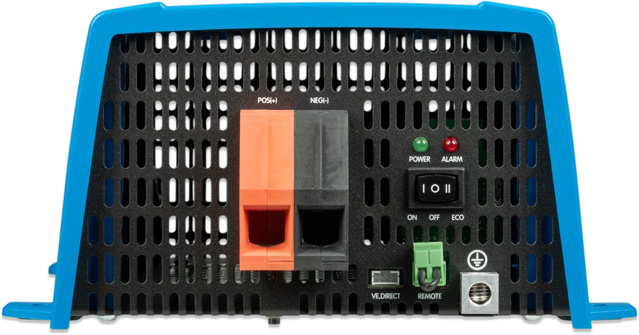
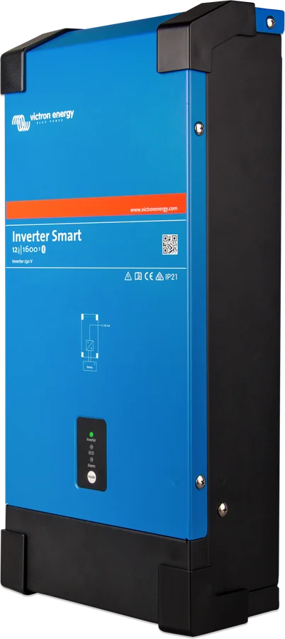
- Which model is it — Inverter Smart has three LEDs on the front (green “inverter”, yellow “ECO” and red “alarm”) and a mode button. Inverter VE.Direct has two LEDs (green POWER and red ALARM) and an ON/OFF/ECO switch next to the battery terminals.
- Warning or alarm — when the green LED is on and the red LED is on or flashing, it is a warning: the inverter is still operating. When the green LED flashes in a fast double pulse, it is an alarm: the inverter has shut down, and the red LED shows the cause.
- App and GX — VictronConnect shows operating status, battery voltage, AC output voltage, load, and warnings and alarms. The app does not run in the background, so it will only notify you of an alarm when it is open. The GX device (e.g. Cerbo GX) shows a message when the inverter reports a warning or alarm. Inverter VE.Direct connects over Bluetooth only with the VE.Direct Bluetooth Smart dongle. Connection problem — see “VictronConnect does not connect over Bluetooth”.
- Interactive decoder — you can also read the Inverter Smart signalling in the LED decoder.
| Red LED | Cause | Step |
|---|---|---|
| steady on | overload | 3 |
| slow flash | low battery voltage | 4 |
| flashing rapidly | battery voltage too high | 5 |
| flashes in a double pulse (on Inverter VE.Direct: a fast double pulse) | overtemperature | 6 |
| flashes in a rapid single pulse (on Inverter VE.Direct: at longer intervals) | DC voltage ripple | 7 |
Installation should be carried out by a qualified electrician. Removing the remote plug from its socket switches the inverter off so that it cannot be turned on by the switch, button or via Bluetooth — the manual recommends removing it during installation. Reversing the battery polarity (plus to minus) damages the inverter. Inverter Smart has no internal fuse — the DC fuse must be fitted externally.
02Step-by-step diagnosis
1Are all LEDs off?
According to the manual, the inverter is then switched off — directly or via the remote connector — or it has no supply. Check the following in order:
- Inverter Smart — press the mode button once. Further presses in quick succession switch between ON, ECO and OFF. The 5000 VA model also has a main switch on the underside, on the right, next to the battery cable inputs — in the OFF position it completely disconnects the supply.
- Inverter VE.Direct — the switch must be in the ON or ECO position. Move it to OFF and back to ON.
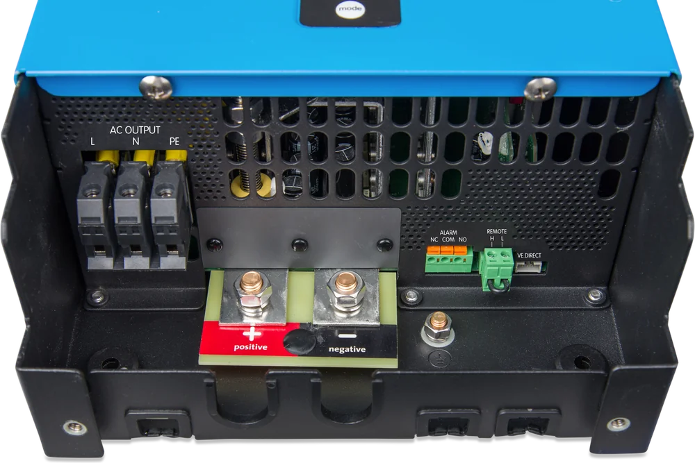
- Remote connector — the inverter in ON or ECO turns on when H and L are shorted together (by the factory jumper, a switch or the Inverter Control panel), H is connected to battery positive or L to battery negative. Check that the jumper is in place and that the switch or remote panel is on. If the remote connector is controlled by the vehicle ignition switch or a lithium battery BMS, the inverter operates only when they allow it.
- Switched off from the app — on Inverter Smart, an inverter switched off by Bluetooth or by the button cannot be switched on or off via the wired VE.Direct port, for example from a GX device.
- DC supply — measure the voltage at the inverter battery terminals. If there is none, check the cables, connections and external fuses. On Inverter VE.Direct, a blown internal fuse means the inverter must be returned for service.
In both manuals, the description of the remote connector sometimes calls the H pin the left one and sometimes the right one. In the Inverter Smart photo in this step, H is on the left — before connecting, check the markings on your unit’s enclosure.
Contact the dealer or installer — see “When it is a hardware fault”.
Go to step 2 and read the indication from the table above.
2In ECO mode, does the inverter keep switching on and off?
When there is no load or a very small one, the inverter in ECO mode goes into search mode: it is off and switches on briefly every 3 seconds to check whether a load has appeared. Self-consumption with no load then drops by about 85%. On Inverter Smart the green LED flashes and the yellow ECO LED lights; on Inverter VE.Direct the green POWER LED flashes slowly in a short pulse.
If the inverter keeps switching on and off even though a load is connected, the manual says the load is too small for the ECO settings. Increase the load or lower the wake-up threshold (“Wake up power”) in VictronConnect. Factory settings:
- Inverter Smart — wake-up threshold 60 VA, sleep threshold 50 VA (both from 0 VA to rated power), retry interval 3 s (0–64 s), test duration 0.16 s (0.08–5 s);
- Inverter VE.Direct — minimum wake-up power 15 W (from 15 W to rated power), interval 3 s (0–64 s), test duration 0.16 s (0.08–5 s). The technical data table for this model gives a 2.5 s interval for ECO mode consumption.
According to the manual, the correct ECO settings depend heavily on the type of load — inductive, capacitive or non-linear — and may need adjustment. The manual reserves changes to the settings for a qualified person. If the load must operate continuously, switch the inverter from ECO to ON.
Lower the wake-up threshold or increase the load; if necessary, use ON mode.
Go to step 3 and check what the red LED shows.
3The red LED is on continuously — overload?
- Warning (green on) — the AC load is greater than the inverter’s rated power. If this continues, the inverter will shut down with an overload alarm. Reduce the load.
- Alarm (green flashes in a fast double pulse) — the inverter shut down after a prolonged overload and will not restart by itself. Remove the cause, then switch the inverter off and on.
How the protection works: motors and pumps draw a high current at start-up, which may exceed the inverter’s overcurrent threshold. The inverter then quickly reduces the output voltage to limit the current. If the threshold is exceeded continuously, the inverter shuts down, waits 30 seconds and starts again. After 3 restarts, if an overload occurs again within 30 seconds of a restart, it remains off.
Continuous power output falls with temperature — for example, Inverter Smart 1600 VA delivers 1300 W at 25 °C, 1200 W at 40 °C and 800 W at 65 °C, while on Inverter VE.Direct power drops by 1.25% for each degree above 40 °C. Data for all models: Inverter Smart and Inverter VE.Direct.
Inverter VE.Direct has no AC output fuse: the cables are protected by a fast short-circuit current limiter and overload detection, which works like a fuse (the greater the overload, the faster the shutdown). The manual for this model also forbids connecting the AC output to another source, such as a mains socket or generator.
4The red LED flashes slowly — low battery voltage?
- Warning (green on) — the voltage has fallen below the “Low battery alarm” threshold. Charge the battery or switch off some AC loads. Also check that the battery cable connections are tight, the cables have sufficient cross-section and the battery is charged and in good condition.
- Alarm (green flashes in a fast double pulse) — the inverter shut down because of low voltage. Measure the voltage at the inverter battery terminals, check the DC fuses, cables and connections.
After switching off, the inverter restarts by itself, at the earliest after 30 seconds, when the voltage rises above the “Low battery restart” threshold. After three restarts, if it shuts down again due to low voltage within 30 seconds, it remains off. Then switch it off and on again or charge the battery — the inverter will restart by itself when the voltage stays above the “Charge detect” threshold for at least 30 seconds.
| System | Shutdown | Restart and alarm | Charging detection |
|---|---|---|---|
| 12 V | 9.3 V | 10.9 V | 14.0 V |
| 24 V | 18.6 V | 21.8 V | 28.0 V |
| 48 V | 37.2 V | 36.6 V (Smart) 43.6 V (VE.Direct) | 56.0 V |
Factory defaults; you change them in VictronConnect. For 48 V, the Inverter Smart manual gives a restart threshold of 36.6 V — lower than the shut-down threshold of 37.2 V — and the Inverter VE.Direct datasheet gives 43.6 V. Check the actual setting in the app. The settings table in the Inverter VE.Direct manual covers only 12 V; the values for 24 and 48 V come from its datasheet.
Dynamic cut-off (disabled by default) sets the shut-down threshold according to the current drawn from the battery: at high current the threshold is lower (10 V in the manual’s example), and at low current it is higher (11.5 V). According to the manual, it is most useful with OPzV and OPzS batteries, less so with GEL and AGM, and with lithium batteries it may not matter. Do not use it if other loads are connected to the same battery — the inverter does not take their consumption into account and will shut down too early with a low-voltage alarm.
With a lithium battery, also check its state — see “Deeply discharged lithium battery”.
5Red LED flashes rapidly — battery voltage too high?
- Warning (green on) — battery voltage is too high; if it rises further, the inverter will shut down.
- Alarm (green flashes with rapid double pulses) — the inverter has shut down, waits 30 seconds and returns to operation automatically when the voltage drops to the correct level.
What to check according to the manual: whether the battery voltage is correct for the inverter, whether the battery bank is connected correctly, and whether any charger, alternator or solar controller is faulty or incorrectly configured. The input voltage range in the datasheet ends at 17 V, 34 V and 68 V (Inverter Smart 12, 24 and 48 V) and 17 V, 34 V and 62 V (Inverter VE.Direct).
6Red LED flashes with double pulses — overheating?
- Warning (green on) — the internal temperature is too high. Reduce the AC load or move the inverter to a better ventilated location.
- Alarm (green flashes with rapid double pulses) — the inverter has shut down, waits 30 seconds and switches back on automatically when it has cooled down.
The manual usually points to excessive ambient temperature, often together with a heavy load. Installation rules from the manual:
- at least 10 cm of free space all around, do not obstruct airflow, do not place in direct sunlight, in a dry, well-ventilated place, never directly above the battery;
- Inverter Smart is designed to be mounted vertically on a wall — it can also be mounted horizontally or laid flat, but cooling is then worse. The manual recommends an ambient temperature from −20 to 40 °C (for Inverter VE.Direct: from −40 to 65 °C);
- mount Inverter VE.Direct on a base, vertically with the fan at the bottom, or horizontally on a wall — not under the ceiling and not with the fan at the top;
- in Inverter Smart, the programmable relay in “Fan” mode switches on when the internal fan is running — the manual gives it as a way to control an external fan when mounted in a small enclosed space.
Under extreme conditions, the enclosure can exceed 70 °C.
7Red LED flashes with rapid single pulses — DC ripple?
- Warning (green on) — the DC voltage ripple is too high; if it rises further, the inverter will shut down.
- Alarm (green flashes with rapid double pulses) — the inverter has shut down, waits 30 seconds and switches back on. If the ripple is still too high after 3 restarts, it stays off — then switch it off and on again.
According to the manual, ripple is linked to voltage drop on the battery cables, and is usually caused by loose DC connections or cables that are too thin. Check the cables between the battery and the inverter: whether they have the recommended cross-section, whether all connections are tightened, and whether the battery fuses and disconnectors are working properly. Persistent high ripple shortens the inverter’s service life.
- Install the inverter as close to the battery as possible to reduce cable losses.
- Inverter Smart: tighten the terminals with an insulated socket spanner, to a maximum torque of 11 Nm. Do not run the battery cables in a closed duct.
- Inverter VE.Direct: the maximum cable cross-section for the terminals is given in the product data sheet.
| Inverter Smart | Cross-section 0–5 m | Cross-section 5–10 m | Fuse | Battery capacity |
|---|---|---|---|---|
| 12/1600 | 1 × 70 mm² | not recommended | 250 A | 300–800 Ah |
| 24/1600 | 1 × 35 mm² | 1 × 70 mm² | 125 A | 150–400 Ah |
| 48/1600 | 1 × 16 mm² | 1 × 25 mm² | 60 A | 75–200 Ah |
| 12/2000 | 1 × 70 mm² | not recommended | 300 A | 350–1000 Ah |
| 24/2000 | 1 × 50 mm² | 1 × 95 mm² | 150 A | 200–500 Ah |
| 48/2000 | 1 × 25 mm² | 1 × 50 mm² | 80 A | 100–250 Ah |
| 12/3000 | 1 × 90 mm² | 2 × 70 mm² | 400 A | 400–1200 Ah |
| 24/3000 | 1 × 50 mm² | 2 × 50 mm² | 250 A | 200–700 Ah |
| 48/3000 | 1 × 35 mm² | 2 × 35 mm² | 125 A | 100–400 Ah |
| 24/5000 | 1 × 90 mm² | 2 × 95 mm² | 400 A | 300–1500 Ah |
| 48/5000 | 1 × 70 mm² | 2 × 70 mm² | 200 A | 150–700 Ah |
With two cables per pole, each one must be able to carry the fuse current without overheating. Selection rules: cable cross-sections and DC fuses, calculator.
8Green and red LED flashing together or alternately?
- Inverter Smart — green and red flashing: the inverter is off, a firmware update is in progress, or the update failed. If it failed, repeat it.
- Inverter VE.Direct — fast alternating: an update is in progress, wait for it to finish; if it fails, repeat it. Slow alternating: calibration or parameter error — the manual says to contact your Victron supplier (fault).
You can start the update in VictronConnect: inverter settings (gear icon) → three-dot menu → “Product settings” — the firmware section shows the version and the update button. In the same menu there is a “Reset to defaults” option, which restores factory settings. More: firmware update.
03Not a fault
- Flashing in ECO mode — in search mode the green LED flashes, and the inverter switches on briefly every few seconds (step 2).
- Brief drop in 230 V during motor or pump start-up — the inverter limits the inrush current this way (step 3).
- The inverter returns to operation by itself after a temperature or high-voltage alarm — after 30 seconds at the earliest, when the cause has cleared (steps 5 and 6).
- No alarm notification on the phone — VictronConnect does not run in the background.
- Hot enclosure — under extreme conditions it can exceed 70 °C.
The inverter/charger shuts down under load — see “MultiPlus reports overload”.
04When it is a hardware fault
The Inverter VE.Direct manual sends you directly to service for a blown internal fuse, and to your supplier for a calibration or parameter error (the LEDs flash slowly alternately). If the LEDs are off despite voltage at the terminals and a correct remote connection, or the inverter still shuts down even though the causes from steps 3–7 have been removed — contact the seller or installer. Have ready the model and serial number, firmware version, description of the LED indications (which LEDs are on, how they flash), messages from VictronConnect or the GX device, the voltage at the inverter battery terminals, the battery type and capacity, cable cross-section and length, fuse rating, and the list of loads powered.
Devices this applies to
 Inverter Smart (Phoenix)Stand-alone 1600–5000 VA inverter with Bluetooth and ECO mode — without a charger.
 Phoenix Inverter VE.DirectSmall 230 V inverter 250–1600 VA — without a charger, with ECO mode and a VE.Direct port.
 VE.Direct Bluetooth dongleBluetooth dongle for the VE.Direct port — gives view and settings on your phone for devices without built-in Bluetooth.
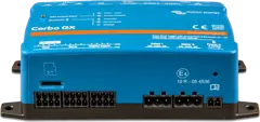 Cerbo GXSystem control centre and gateway to the VRM portal.
Sources
- Inverter Smart Manual — chapter 5: LEDs and troubleshooting (5.2), protections and automatic restarts (5.3) (HTML version, as of 21 September 2026)victronenergy.com · EN
- Inverter Smart Manual — chapter 4: ECO mode (4.2), battery thresholds and Dynamic cut off (4.3), relay (4.4)victronenergy.com · EN
- Inverter Smart Manual — chapter 3: mounting location, battery connection (3.2.1), remote connection (3.2.3)victronenergy.com · EN
- Inverter Smart Manual — ch. 6: technical datavictronenergy.com · EN
- Inverter VE.Direct 230V Manual (HW15) — ch. 5: LEDs (5.2), protections and automatic restarts (5.3) (HTML version, state as of 21 September 2026)victronenergy.com · EN
- Inverter VE.Direct 230V Manual (HW15) — ch. 4: ECO mode, battery thresholds, Dynamic cut offvictronenergy.com · EN
- Inverter VE.Direct 230V Manual (HW15) — ch. 3: installation, AC output, remote connectorvictronenergy.com · EN
- Inverter VE.Direct 230V Manual (HW15) — ch. 6: technical datavictronenergy.com · EN