
01First check
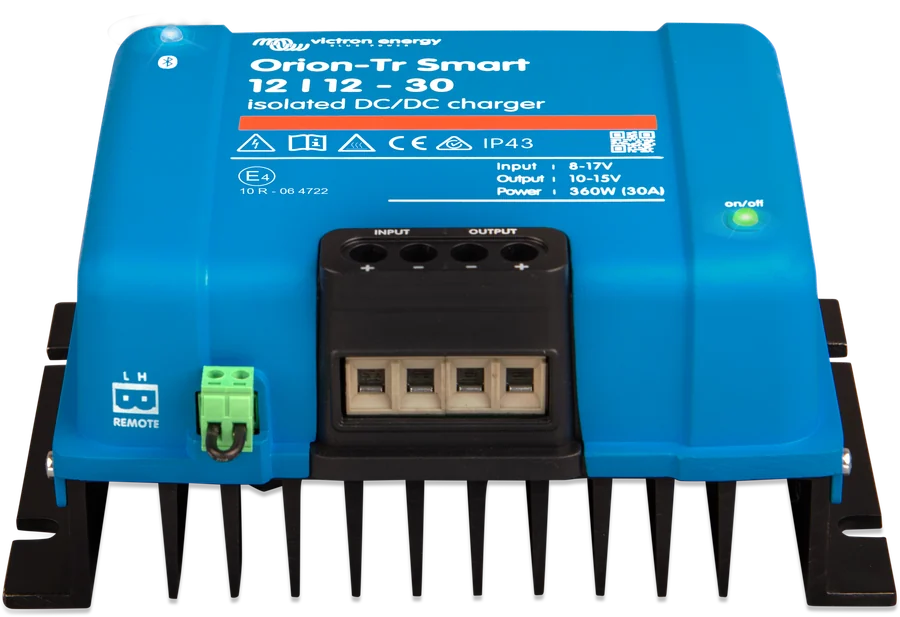
- Operating mode — Orion-Tr Smart works as a charger (three stages: Bulk, Absorption, Float) or as a constant-voltage power supply. A power supply does not use a charging algorithm, and its output voltage may be set too low — to charge batteries, the “Charger” function must be selected in the settings.
- STATUS screen in VictronConnect — shows the charger state, input and output voltage, and when the charger is off — the reason. The app does not show input or output current. Warnings and errors are also visible in the device list without connecting if Instant Readout is enabled.
- Orion XS has a separate manual and different codes — see “Orion XS does not charge”.
| LED | Signal | Meaning |
|---|---|---|
| green | off | no input voltage, remote or user shutdown, connector overtemperature protection, input voltage lock-out or detected engine stop (in charger mode) — steps 1–5 |
| green | on | output active in power supply mode or charger in Float state (battery charged) |
| green | flashes every 0.8 s | Bulk or Absorption — the battery is charging |
| blue | off | no input voltage or Bluetooth turned off — step 9 |
| blue | flashes every 3 s | error — read the code in VictronConnect (step 8) |
| blue | flashes once every 5 s | charger switched off without error: by remote, by user, input voltage lock-out or detected engine stop |
| blue | flashes every 0.8 s | Bluetooth active (chapter 6 describes this as connected, chapter 7.3 — as ready to connect) |
| blue | flashes every 0.4 s | device identification |
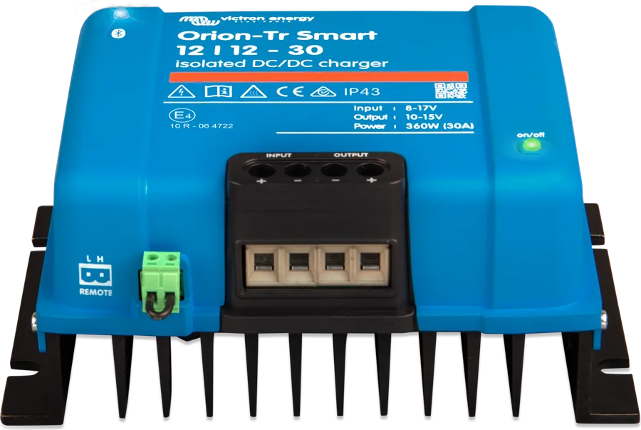
Orion-Tr Smart has no reverse-polarity protection — a device damaged in this way cannot be repaired, and the warranty does not cover such damage. Always check polarity before connecting the battery. The unit is potted and has no internal serviceable parts or replaceable fuses — do not open it. The installation must include an external fuse selected according to the table in step 6.
02Step-by-step diagnosis
1Does the Orion-Tr Smart switch on at all?
A working charger lights or flashes its LEDs and connects to VictronConnect. The Bluetooth circuit is powered by the battery connected to the input — without input voltage both LEDs are off. If nothing lights up:
- inspect the enclosure and terminals — mechanical damage is a likely cause according to the manual;
- check for burn marks and a burnt smell — this is also a likely cause. The unit is potted, so a slight smell while charging is normal when it warms up;
- measure the battery voltage directly at the charger terminals with a multimeter — this rules out cables, fuses and switches in the path from the battery.
| Voltage at the terminals | State | Action to take |
|---|---|---|
| none | disabled | Restore power: check external fuses, loose or damaged cables, and crimping of terminals (pull on the cable). |
| correct | disabled | Possible charger fault — contact the dealer. If the charger was connected with reverse polarity, it must be replaced (no warranty). |
| correct | off because there is no remote connection | Restore the remote connection — step 3. |
Go to step 2.
Follow the table above.
2What does VictronConnect show on the STATUS screen?
The manual recommends starting by checking whether the app gives the reason charging is disabled (the “Off reason” field or the message “Charge is disabled due to: …”).
| Message | Action to take |
|---|---|
| Remote input inactive | Check the remote connector — step 3. |
| Disabled in settings | Enable the charger in the battery settings (switch “Charger enabled”). |
| Engine shutdown detected | The charger has assumed the engine has stopped — step 4. |
| Input voltage lock-out | The input voltage has dropped below the lock-out threshold — step 5. |
If the charger is charging (Bulk, Absorption or Float) and the battery is still not full, go to steps 6 and 7.
3Is the remote connector fitted and shorted?
The minimum for the charger to work is a wire bridge between terminals L and H. Check whether the remote plug is inserted, and with a bridge or simple switch — whether there is continuity between L and H. The manual gives four recommended wiring methods:
- a) a switch between L and H (on when the impedance between them is below 500 kΩ);
- b) a switch between the positive of the input battery (starter battery) and terminal H (on above 3 V);
- c) a switch between terminal L and the negative of the input battery (on below 5 V);
- d) control from the BMS — in the isolated version via the isolated remote wire, in the non-isolated version via terminal H.
Terminals L and H withstand ±70 V DC. If the remote connector is controlled by the BMS, check whether the ATC connection (charge permission) is working. The BMS may also have intentionally blocked charging — see “BMS has cut off charging”.
During installation, the manual says to disconnect remote first (remove the bridge or unplug the connector), configure the unit in VictronConnect and only then reconnect remote — it is what starts the charger.
Go to step 4.
Fit the bridge or repair the connection to the switch or BMS.
4Not charging while driving, or charging stops?
In charger mode, Orion-Tr Smart detects engine running from alternator voltage alone — no additional sensors are needed. A conventional alternator gives a constant voltage (e.g. 14 V), and a smart alternator gives a variable one, from 12.5 V to 15 V; it varies most in regenerative braking systems. Factory settings for the 12 V input (multiply by 2 for 24 V, by 4 for 48 V):
| Setting | Factory value |
|---|---|
| Alternator type | Smart Alternator |
| Charging starts immediately | 14 V |
| Start delay | 13.3 V (smart), 13.8 V (conventional) |
| Start delay | 2 min |
| Shutdown (engine stopped) | 13.1 V (smart), 13.5 V (conventional) |
How it works: when the input voltage drops to the shutdown threshold, the charger reduces the current so it does not fall any lower. If the voltage stays below the threshold for more than one minute, it assumes the engine is stopped and stops charging. Current flowing in the input cable lowers the voltage measured by the charger — input cables that are too thin or too long therefore make it reach the threshold sooner (step 6).
- Does not start charging — the start threshold is set too high for the alternator, which never reaches it. Lower the start threshold and make sure the alternator allows it.
- Stops charging too early — the shutdown threshold is set too high. The operating description in chapter 5 shows that lowering it helps; the table in chapter 7.2 says to “raise” it here — this is an inconsistency in the manual. The shutdown threshold keeps the starter battery charged and creates hysteresis relative to the start threshold; according to the VictronConnect manual, a difference of at least 0.2 V between the thresholds is usually used (for 12 V input).
- Ignition controlled — a voltage above 7 V at the L terminal forces charging regardless of engine running detection (for example from the ignition switch or an engine-running signal from the CAN bus). This does not replace the remote function — the connector must be wired using method a), b) or d) from step 3. After the ignition is switched off, the charger returns to engine-running detection rather than switching off.
- Engine running detection disabled (“forced charging”) — the charger draws current from the starter battery even with the engine off. In this case, only the input voltage lock-out protects it (step 5), so do not set it too low — according to the manual, in most 12 V applications 12.5 V is a sufficiently low threshold.
Engine-running detection works only in charger mode. The mechanism described applies from firmware v1.05 — you can check the version in VictronConnect (Settings → three-dots menu → Firmware).
5“Input voltage lock-out” message?
Input voltage lock-out is the lowest voltage at which charging is allowed — below it, charging stops immediately and resumes once the restart threshold is exceeded. Factory settings for 12 V input: in charger mode, lock-out 12.5 V and restart 12.8 V; in power supply mode, 10.5 V and 12 V. According to the VictronConnect manual, a difference of at least 0.5 V between lock-out and restart is usually used. The manual’s solution: ensure the input voltage is above the restart threshold or disable the lock-out in settings — but with engine-running detection disabled, the lock-out is the only protection for the starter battery.
When setting the lock-out, the manual gives two criteria:
- Lowest alternator voltage — a smart alternator can briefly drop below 12.5 V, for example during acceleration. If charging should continue then, the lock-out must be set below that voltage.
- Voltage drop on the input cable — the lock-out must not trigger before the charger has time to reduce the current: lock-out threshold ≤ shutdown threshold − cable voltage drop. In the manual’s example (5 m to the starter battery, 16 mm² cable, about 1.1 mΩ/m, i.e. 11 mΩ for 2 × 5 m, current draw about 35 A for the 12/12-30 model), the drop is about 0.385 V. The manual subtracts it from 13.3 V, although the shutdown threshold in this example is 13.1 V — at 13.1 V this gives about 12.7 V.
Regardless of this, the charger switches off at very low input voltage: 7 V (restart 7.5 V) for 12 V input, 14 V (15 V) for 24 V and 28 V (30 V) for 48 V.
6Are the cables and terminals in order?
- Check whether the cables are damaged, connections are loose, lugs are badly crimped, and the battery fuse has blown. Is the insulation stripped to the correct length, and are the terminals tightened to the correct torque — 1.6 Nm, held for at least 5 seconds? Never tighten less.
- Use flexible multi-strand copper cable: a single wire must be at most 0.4 mm in diameter (0.125 mm²); a 16 mm² cable should have at least 122 strands (Class 5 or higher). Thicker wires give too little contact area — high contact resistance leads to severe overheating and eventually fire. The maximum terminal size is 16 mm².
- Burn marks on the terminals or melted cables or connectors — the manual says to replace the device; this type of damage is usually not covered by the warranty.
- VictronConnect shows a higher output voltage than you measure at the battery? At high current this is normal, but the same symptom can be caused by a poor connection between the output and the battery — keep the resistance of all connections as low as possible.
- Installation: vertical, terminals down, on a non-flammable surface, with at least 10 cm of free space above and below the device, close to the battery, but never directly above it. The charger has overtemperature protection and reduces output at high temperature — above 40 °C by 3% for every degree (operating range −20 to 55 °C).
| Voltage (input or output) | Fuse | 0.5 m | 1 m | 2 m | 5 m | 10 m |
|---|---|---|---|---|---|---|
| 12 V | 60 A | 6 mm² | 10 mm² | 10 mm² | 16 mm² | 16 mm² |
| 24 V | 30 A | 4 mm² | 6 mm² | 6 mm² | 10 mm² | 10 mm² |
| 48 V | 20 A | 2.5 mm² | 4 mm² | 4 mm² | 6 mm² | 6 mm² |
Minimum cable cross-sections by length and external fuses from section 4.2 of the manual. Selection rules: DC cable cross-sections and fuses.
7Charging, but the battery remains undercharged?
Wrong battery settings may cause the charger to switch to Absorption or Float too early and the battery will not charge fully.
- Check the absorption voltage in the Battery settings and set the value recommended by the battery manufacturer. The preset also sets the Float voltage, Bulk time limit, re-bulk threshold and absorption time — each of these values can be changed.
- Make sure charger mode is selected — power supply mode does not use the charging algorithm, and the output voltage may be set too low.
- Absorption time: for lead-acid batteries, adaptive (short after shallow discharge, longer after deep discharge); for lithium batteries, fixed — 2 hours as standard. With adaptive time, you set the maximum time (at least 30 minutes); with fixed time, you can set any value, even 0.
- In Float, a new charging cycle starts when the battery voltage has been below the re-bulk threshold for at least one minute, for example under heavy load.
If the STATUS screen shows “Input voltage lock-out”, go back to step 5; if charging stops and starts, go to step 4.
8The blue LED flashes every 3 seconds — error code?
You can read the code in VictronConnect. The Orion-Tr Smart manual describes five codes:
| Code | Meaning | Action to take |
|---|---|---|
| Error 2 | battery voltage too high | Clears automatically when the voltage drops. The cause may be another charger charging the battery or a fault in the solar charge controller. |
| Error 26 | overheated power terminals | Check the cables — including their type and strand construction — and, where possible, tighten the screws (step 6). Clears automatically. |
| Error 27 | battery-side short circuit | Overcurrent on the battery side — for example when connecting a battery with a contactor or when the charger starts without a battery, connected to an inverter with high input capacitance. Clears automatically; if not, disconnect all power sources, wait 3 minutes and switch on again. If the fault remains, the charger is probably faulty. |
| Error 116 | calibration data lost | If the device does not work and the error is active — a fault — contact the seller for a replacement. If the error is only in the history and the device works normally, you can ignore it (some units left the factory with this entry). |
| Error 119 | lost settings | It does not clear itself. Restore factory settings (the three-dot menu in VictronConnect), disconnect all power sources, wait 3 minutes, switch it on and set up the charger again. Report this to the seller — according to the manual, this error should not happen. |
For the current list of codes, the manual refers to the common Victron charger code list — you can find descriptions of all codes on the charger and MPPT error codes page.
9Can’t connect via Bluetooth?
- Blue LED off — no input voltage (restore power), Bluetooth permanently disabled in VictronConnect (this setting cannot be undone), or set to “Enabled for 30 seconds”: Bluetooth then works only for 30 seconds after power-up — disconnect and reconnect the input cable and connect within 30 seconds. If none of these fits, the device may be faulty — make a warranty claim.
- Blue LED flashes every 0.8 s — a connection may already be active. Only one phone or tablet can be connected at a time; if Orion is greyed out in the app, another device is connected.
Other connection problems: “VictronConnect does not connect via Bluetooth”.
03Not a fault
- Charging starts with a delay after engine start — at a voltage between the delayed start threshold and the start threshold, the charger waits (2 minutes by default) so the alternator can first replenish the energy used by the starter.
- Charging continues for up to a minute after the engine is switched off — engine stop is detected when the voltage stays below the stop threshold for more than a minute.
- The charger is hot and smells slightly at full power — according to the manual, this is normal; the unit is potted, and the smell is not harmful to health. Do not cover the charger.
- Output voltage in the app is higher than on the battery — at high current this is normal (step 6).
- No current in the app — VictronConnect does not show this charger’s input or output current.
04When it is a hardware fault
According to the manual: the charger does not switch on despite correct voltage at the terminals and a proper remote connection; error 27 does not clear after disconnecting power for 3 minutes; error 116 is active and the device does not work; the blue LED is off with none of the reasons from step 9. A device damaged by reverse polarity cannot be repaired. In such cases, contact the seller or installer. Have the model ready (for example, 12/12-30, isolated or non-isolated), serial number, firmware version, STATUS screenshot with the shutdown reason, settings (operating mode, battery, engine running detection, voltage lockout), input and output terminal voltages, alternator type, and cable cross-sections and lengths and fuse ratings.
Devices this applies to
Sources
- Orion-Tr Smart DC-DC Charger Isolated — chapter 7: troubleshooting and error codes (HTML version, as of 21 September 2026)victronenergy.com · EN
- Orion-Tr Smart DC-DC Charger Isolated — chapter 5: engine running detection and input voltage lockoutvictronenergy.com · EN
- Orion-Tr Smart DC-DC Charger Isolated — chapter 6: LEDsvictronenergy.com · EN
- Orion-Tr Smart DC-DC Charger Isolated — chapter 4: installation, cables and fuses, polarity, remotevictronenergy.com · EN
- Orion-Tr Smart DC-DC Charger Isolated — chapter 9: VictronConnect (STATUS, battery settings, Bluetooth)victronenergy.com · EN
- Orion-Tr Smart DC-DC Charger Isolated — chapter 8: technical datavictronenergy.com · EN
- Orion-Tr Smart DC-DC Charger Non-Isolated — chapter 7: troubleshooting (HTML version, as of 21 September 2026)victronenergy.com · EN
- Orion-Tr Smart DC-DC Charger Non-Isolated — chapter 4: installation, BMS control via H contactvictronenergy.com · EN