

011. Design — before you buy anything
- Energy balance. List the 12 V and 230 V loads, their power and how long they run per day — this determines battery capacity and how much the panels will produce in a given month. This is calculated by the energy balance calculator; details in the campervan energy balance.
- System voltage. Victron’s recommended maximum inverter power: 12 V — up to 3000 VA, 24 V — up to 5000 VA, 48 V — above that. In a typical campervan, 12 V is enough.
- Battery type. A “drop-in” battery with built-in BMS, for example SuperPack NG — simpler, as in the campervan diagram. A battery with an external BMS (Lithium Smart, Lithium NG) — the BMS controls the chargers and loads, as in the workshop van and on the yacht. Connecting multiple batteries: battery bank.
- Charging sources. Panels with an MPPT charge controller (choosing an MPPT for panels), alternator via a DC-DC charger and campsite hook-up via a battery charger or inverter/charger (choosing an inverter). In winter, panels in Poland produce only a fraction of their summer output, so the plan must also rely on the alternator and campsite hook-up.
- Location in the vehicle. Battery in the heated part of the conversion — do not charge LiFePO4 batteries in frost: Victron LiFePO4 Smart accepts charging only from +5 °C to +50 °C, and for batteries from other manufacturers their datasheet gives the range. Inverter and chargers with airflow; all fuses and the main switch in one accessible place. See layout in a campervan.
022. Mechanical installation
- First the cable entries and cable runs: from the roof panels, from the starter battery, from the 230 V external inlet — before the furniture goes in, while access is still easy.
- Battery low down and securely mounted, inverter next to it with free space around it; DC-DC charger close to the starter battery, MPPT charge controller close to the battery — installation in a campervan.
- Roof panels with a sealed cable entry, and a PV isolator at the controller.
033. DC wiring
- Cross-sections before buying cable. Voltage drop no more than 2.5% — cable calculator. Example from Victron’s diagram for a MultiPlus 3 kVA 12 V: at a distance of 0–5 m from the battery, 4 × 50 mm² and a 400 A fuse; in enclosed trunking and conduits, double the cross-section. All values: cables and fuses for campervans.
- Fuse every positive. Every load and every source has its own fuse; with a lithium battery, at least one must have a breaking capacity no lower than the battery short-circuit current (e.g. Class-T) — DC cable cross-sections and fuses.
- Negatives through the battery monitor. SmartShunt or BMV-712 in the battery negative, and all load and charger negatives on the “system minus” side. Orion negative, engine negative and starter battery negative — to the central negative busbar.
- Fuses removed. During all wiring, the main fuses are left out and the main switch is off.
044. 230 V wiring
- External inlet, then the breaker and residual current device, then the inverter/charger AC input. At a campsite the shore power connection is usually 16 A — set the input current limit to match.
- On each AC output, fit an RCD with overcurrent protection. Size the AC-out-1 cables and protection according to the sum of the input current and the current added by PowerAssist. When the inverter is operating, the neutral conductor must be connected to earth — earthing and RCD.
- Have the 230 V installation carried out and checked by a qualified electrician.
055. Commissioning
- Check the connections. Polarity, terminal tightness, crimping of the cable ends — before any voltage is applied.
- Main fuses last. Only after checking, insert the main fuses and switch on the main switch. MPPT solar charge controller: battery first, wait 10 s, then loads and panels.
- Update and settings. Update the software of all devices, set the charge profiles for the lithium battery and enter the battery capacity in the monitor. On the Orion XS, set Li-Ion mode and start/stop according to a standard or smart alternator — for Euro 6 vehicles, see Orion XS and Euro 6.
- Test every source. Check, one by one, charging from shore power, from solar panels and from the alternator, and inverter operation without mains. The battery monitor or Cerbo GX will show the status of everything.
- RCDs. Use the test button to check each RCD — also when running from battery, with no shore power.
06Most common mistakes
- Load negative connected directly to the battery, bypassing the shunt — the monitor shows an artificially high state of charge (details).
- Cables to the inverter that are too long and too thin — low-voltage alarms and cable heating.
- Charging a lithium battery in freezing temperatures without a lockout — LiFePO₄ in winter.
- No RCD after the inverter, or no N–PE link when the inverter is operating — the RCD is there, but it does not protect.
- Powering control devices (dongle, GX) before the main switch — they drain the battery during storage.
230 V and high DC currents
You can prepare the conceptual design yourself, but AC and DC electrical work — especially with 230 V and high DC currents — should be carried out and checked by a qualified electrician or technician in line with local requirements.
Devices in this guide
 MultiPlusInverter/charger 800 VA–20 kW: PowerAssist, UPS under 20 ms, parallel and three-phase operation.
 Lithium SuperPack NGDrop-in LiFePO4 battery with built-in BMS, heater and IP65 — a simple replacement for a lead-acid battery in a campervan.
 SmartSolar MPPT 100/30 and 100/5030 and 50 A controllers for up to 100 V from panels — at 12 V for about 440 and 700 W of panels.
 Orion XSDC-DC charger 50/70 A from the alternator, including with a smart alternator.
 SmartShuntBattery monitor with 300–2000 A shunt, read on your phone or on a GX device.
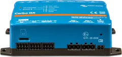 Cerbo GXSystem control centre and gateway to the VRM portal.